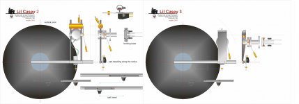
The support structure dosen't even have to be left of the center spindle, it could be like 45 mm to the right and the other part of it also just 45 mm outside the platter (could be even closer maybe just 20mm). The radial rail tube is outside the support structure (the rail is longer than the cartridge travel for obvious reasons).
Hi Koldby, after the drawing of # 2355 I did these two, then the parallelogram came to mind, and I abandoned it.
The carriage used in the mockup, derived from the # 2360 attempt, wasn't bad at all: simple, light and allowing both articulations. Using the same carriage the mockup showed clearly the advantage of a radial rail, without the shaft's unfavorable lever: in the #2360 attempt there was a bit of stylus bending, not visible in that rough test.
I've really appreciated the clever neatness of your arm: to design a linear tracker using only one profile means having clear ideas. The advantage of big balls (elsewhere not always demonstrable 🙂) maybe derives from the section of the rail: greater diameter = smaller lateral thrust.
Even the advantage to better overcome the small roughness of the anodization may have a role
carlo
Attachments
Hi Koldby, after the drawing of # 2355 I did these two, then the parallelogram came to mind, and I abandoned it.
The carriage used in the mockup, derived from the # 2360 attempt, wasn't bad at all: simple, light and allowing both articulations. Using the same carriage the mockup showed clearly the advantage of a radial rail, without the shaft's unfavorable lever: in the #2360 attempt there was a bit of stylus bending, not visible in that rough test.
I've really appreciated the clever neatness of your arm: to design a linear tracker using only one profile means having clear ideas. The advantage of big balls (elsewhere not always demonstrable 🙂) maybe derives from the section of the rail: greater diameter = smaller lateral thrust.
Even the advantage to better overcome the small roughness of the anodization may have a role
carlo
Thanks a lot , Carlo.
Means a lot coming from you, as you are the one with the clever ideas and thinking out of the box. The disadvantage with the bigger balls (I will leave the clever remarks on this sentence to public imagination 😀) is the higher weight that could lead to higher stiction and certainly higher inertia. But as you say, and what I observed also less friction when first in movement
I certainly can appreciate the rail in # 2360, but cannot be used in my suggestion, as I plan to support the rail tube with supports as close to each other as possible, still allowing the carriage to move from in-lead groove to out-lead groove
Carlo! Thanks again for your inventiveness and graphic skill. The "Lil Casey 3" is getting close to what I have in mind. One thing I hesitated in building a parallel tracker is that I absolutely hate having a fixed structure hovering over the platter. So inconvenient so aesthetically unpleasing. I have to think of myself as a user! It's one of my pet peeves and that's what prompted me into the pivoting tangential tonearm a la Birch and Thales, etc... in my other thread.
Now, if we can only make the carriage slide out of the platter when not in use, that would be great. Since we need at least 4 inches of travel from outer groove to inner groove, we need a 4 inch arm tube with cartridge at one end and the other end rolling system or carriage. We need to need a counterweight on that rolling end so the mass is not too high. Here's what I have in mind... We need a horizontal double edge blade, one V-groove ball bearing on top and one V-groove ball bearing at bottom, the 4 inch arm tube is tied to between these two rollers, which are an inch apart horizontally. This arrangement limits any axial movement and both rollers are loaded. So the cartridge is cantilevered from the carriage and travel from outer groove to inner groove, total 4 inches of travel. I hope this makes sense without any drawing.
Early on, I even thought of using a sliding rod (a la Maplenoll airbearing arms or ET arms) but the mass would keep changing on either end so I scrapped that idea. One advantage of having the vertical bearing outside of the platter area is that the vertical bearing point can be at the plane of the platter which can help playing warp records better with such short arm.
Another question I have is has anyone use a parallel tracker with a diagonal arm tube with offset angle at the headshell and bearing so the cartridge is on the platter side but the bearing is outside of the platter? This way there's no permanent fixed hovering structure over the platter.
Last edited:
I'm afraid it would bring back the dreaded skating force.Another question I have is has anyone use a parallel tracker with a diagonal arm tube with offset angle at the headshell and bearing so the cartridge is on the platter side but the bearing is outside of the platter? This way there's no permanent fixed hovering structure over the platter.
I'm afraid it would bring back the dreaded skating force.
Even with no horizontal pivot? I'm excluding servo arms, obviously.
Last edited:
..... I absolutely hate having a fixed structure hovering over the platter. So inconvenient so aesthetically unpleasing. I have to think of myself as a user!
fully agree, Direct driver.
That's the reason to design the parallelogram version of the LilCasey, that rotates on its base, and is used exactly like any well born tonearm. (LilCasey mk1 #2440 #2470 -- LilCasey - mk2 carbon #2875 #2906)
Unfortunately a complete disaster as a status symbol/conversation piece, so different from those goldy monuments, so high-endish. No one will realize that you have changed your old tonearm: commercially an announced failure.
The parallelogram solution has two main reasons: a much greater lightness achieved with a simple and unusual mechanics - no variation of VTA because now even the vertical movement is parallel.
I might be proud, because it's the first TA to have it (so called linear trackers are just half-linear trackers...), but I confess I can't feel any improvement in sound due this.
On the other hand, with respect to those first ideas, it asks for a far greater precision: but let's say we're here for that.
carlo
Last edited:
In my own mind, there are ways to...
NOT use parallelogram and...
NOT use a rotating base in order to...
NOT have a fixed structure hovering over the platter.
Although my previous post explains how I want to do it and it's diy-able but I still need to just get my lazy butt to make a drawing!
I understand your point of view Dd, and certainly a radial rail is not the solution you are looking for.
I have tried to interpret your description but, as far as I can understand (attachment), there seem to emerge counteracting forces that would certainly not favor the carriage's advancement.
On common LTs we try to shorten the shaft's lever and lengthen the carriage in order to have > theta; here instead r increases due to the asymmetry of the 4" rod, and virtual pivot position.
ciao carlo
Attachments

I have tried to interpret your description but, as far as I can understand (attachment), there seem to emerge counteracting forces that would certainly not favor the carriage's advancement.
I notice there are some typos on my original post. Major error being that the sliding assembly should have NO counterweight. Again, NO counterweight. Sorry for the confusion. The stylus and the 4 inch arm tube and midpoint of two V-groove rollers (carriage) are in line with the radius. It moves only laterally. The whole assembly has no vertical pivot and only slides left and right. The vertical pivot is placed 3 inches behind and is similar to your Lil Casey 3.
Last edited:
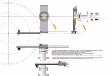
Hi Dd, another attempt, hoping to be nearer to your idea.
Carlo, thank you again for your brilliant graphics.
The arm tube should be below the V-groove rollers and the horizontal blade. The top roller to the arm tube to the lower roller form an "L" shape. From stylus tip to the tube to the midpoint of V-groove and blade are all in line (in vertical plane) with the radius. So the rollers are right above the tube, which should really be 5" long. As you can see the whole assembly deals with horizontal movement only so there shouldn't be any twisting forces that you mentioned.
Since this is a really short arm in the vertical plane, 3 inches or shorter, it is important to place the vertical pivot on the same plane as the stylus and platter/record surface to deal with warp records easier. That's one of the main benefits of not doing the hovering over the platter design so the vertical bearings can finally be placed on platter level.
I do not like gimbal bearings for vertical movement and I prefer the vertical bearings be two spikes a la Kuzma 4Point style. That way the two bearing points (2 ball point pen tips?) are always loaded, lower contact area, low friction, and much simpler and cheaper.
I like the visual aspects of your Lil Casey 3 and it's stylish but for a diy project I would use something smaller to lessen the vertical mass. A short tube and conventional counterweight is suffice.
The joint or attachment between the vertical arm to the blade requires some tweaking and more creative thinking that hopefully can do the following:
(1) lessen vertical mass
(2) increase rigidity
(3) and most importantly, SAME even track force in the horizontal arm's entire 4 inch travel!! (Parallelogram Roberval balance again?)
Obviously the easiest solution to lessen vertical mass is to shorten the horizontal arm from 4 inches to, say, 2 inches and that would make the blade to hover over the platter again but that's something I don't want to give up. If you're a perfectionist, then make the horizontal arm as short as possible. Others can certainly try. Feel free to chime in and welcome any advice you may have.
Thanks again, Carlo!
So the rollers are right above the tube, which should really be 5" long.
CORRECTION: the tube is below the top roller and blade but the lower roller should be next to the right end of the tube. So the top roller and tie point of tube and bottom roller should form an "L" shape.
vertical pivot
Another advantage of using two spikes pointing down as vertical bearings is that the spikes can be on set screws so you can use them to adjust VTA, if you want, and the leveling of the horizontal elements and even cartridge azimuth (not recommended). One contact point should be stationery, spike in a dimple. Another contact point can be on tiny V groove to adjust balance (similar to Kuzma 4Point). Again, the pivot point should be on the same plane as the platter or record surface and that's the main reason I want the assembly outside of the platter beside not wanting structure hovering over the platter. It's more than just aesthetic reason.
I notice many hovering parallel trackers employing arms with effective length as short as only 2 inches. The Clearaudio arms are 61.7mm and the Versa Dynamics arm is even shorter so I think a short vertical arm on this design can be just as short and since the pivot point is at platter level, tracking warp records should not be a problem, I hope. So instead of the 3 inch length I proposed earlier, I would make it even shorter to 2" or 50mm, which will drop the vertical mass another notch.
Since this is a really short arm in the vertical plane, 3 inches or shorter, it is important to place the vertical pivot on the same plane as the stylus and platter/record surface to deal with warp records easier. That's one of the main benefits of not doing the hovering over the platter design so the vertical bearings can finally be placed on platter level.
I do not like gimbal bearings for vertical movement and I prefer the vertical bearings be two spikes a la Kuzma 4Point style. That way the two bearing points (2 ball point pen tips?) are always loaded, lower contact area, low friction, and much simpler and cheaper.
Another advantage of using two spikes pointing down as vertical bearings is that the spikes can be on set screws so you can use them to adjust VTA, if you want, and the leveling of the horizontal elements and even cartridge azimuth (not recommended). One contact point should be stationery, spike in a dimple. Another contact point can be on tiny V groove to adjust balance (similar to Kuzma 4Point). Again, the pivot point should be on the same plane as the platter or record surface and that's the main reason I want the assembly outside of the platter beside not wanting structure hovering over the platter. It's more than just aesthetic reason.
I notice many hovering parallel trackers employing arms with effective length as short as only 2 inches. The Clearaudio arms are 61.7mm and the Versa Dynamics arm is even shorter so I think a short vertical arm on this design can be just as short and since the pivot point is at platter level, tracking warp records should not be a problem, I hope. So instead of the 3 inch length I proposed earlier, I would make it even shorter to 2" or 50mm, which will drop the vertical mass another notch.
CORRECTION: the tube is below the top roller and blade but the lower roller should be next to the right end of the tube. So the top roller and tie point of tube and bottom roller should form an "L" shape.
Roughly something like this for the horizontal carriage.

Another advantage of using two spikes pointing down as vertical bearings is that the spikes can be on set screws so you can use them to adjust VTA, if you want, and the leveling of the horizontal elements and even cartridge azimuth (not recommended). One contact point should be stationery, spike in a dimple. Another contact point can be on tiny V groove to adjust balance (similar to Kuzma 4Point). Again, the pivot point should be on the same plane as the platter or record surface and that's the main reason I want the assembly outside of the platter beside not wanting structure hovering over the platter. It's more than just aesthetic reason.
Another rough idea of the vertical pivot. You can use spikes, set screws, gimbal, or even ball bearings, etc... as long as the pivot is on the same level with the platter.
Included also headshell idea.

Last edited:
Oops
Some drawing errors in the last post. Here's a better one.
I also should add a fluid damping trough below the blade in case that's required. You get the idea!

Some drawing errors in the last post. Here's a better one.
I also should add a fluid damping trough below the blade in case that's required. You get the idea!
Last edited:
another version
I keep butchering Carlo's drawing. Sorry.
The counterweight obvious will be behind bottom bar at midpoint, not in drawing.
Hell, you can even use an L shape aluminum bracket for the vertical assembly.

I keep butchering Carlo's drawing. Sorry.
The counterweight obvious will be behind bottom bar at midpoint, not in drawing.
Hell, you can even use an L shape aluminum bracket for the vertical assembly.
Last edited:
Such a structure may not be desirable because of the combined weight of the cartridge and headshell is amplified by the arm tube. Therefore, the pressure of v groove bearings on the knife-edge rail will increase. In other words, the friction will increase.
A short arm may be a good option, however, there will be a structure over the LP.
A short arm may be a good option, however, there will be a structure over the LP.
Last edited:
It's a pleasure for me to explore new ideas, Dd.
That's just a scheme roughly assembled, very far from a real design. Lot of work in sight. Therefore, before focusing on details, some sensations based on the construction and tests of some previous TAs, about some possible problems.
design
initially I thought it was more similar to a Mapleknoll, but this instead is also a radial rail, so the aligned side force works at it's best, without generating any torque.
the stylus drag instead works badly: there is a long lever that multiplies torque and friction on the roller bearings, with possible locking (I can't forget the similar kind of issue on Syrinx PLT). Or at least a "negative skating".
construction
the "sliding drawer" bearing is a smart solution, because it avoids the variation of the VTF. However, roller ball bearings on LTs are already at the limit, and here the 4" cantilever multiplies the weight on them. I'll think about it.
The weight of the tube + bearings + blade + vertical shaft + CW will certainly not be small: halving the vert. eff mass on Lil Casey carbon (= 19.3 grams) compared to MK1 was substantial on warps. Here, going down to acceptable levels for modern cartridge compliance does not seem easy at all.
Vertical articulation: here it must be taken into account that the cantilevered tube + asymmetric double blade introduce a variable load on the 2 sides of this articulation: therefore knife blades, spikes etc are imho not usable; for the necessary stiffness even jewells may not be enough, needing excellent ball bearings.
I learned at my expense that the alignment of the joints to the tip (like the CW center of gravity), so commercially unusual, is instead very important for a clean sound. My best sounding TAs: (the 3points, an unipivot and even a strange gimbal) seriously follow this principle. Here it should not give too many problems.
I would not shorten the shaft (3" is already very short, from my point of view) and even less the cantilever tube.
No platter hovering was the starting point, isn't it? otherwise why not buying a Clear Audio ?...
carlo
my compliments for your new graphic skills
Last edited:
- Home
- Source & Line
- Analogue Source
- DIY linear tonearm