...Balls seem to be ideal, they work so great... -- off topic.
Walter, Eduard: Lil Casey sounds good, but this (attachment) sounds better. By far the best i've built in ten years. Seems a common pivoted, but looking inside it differs from the others at least as much as the radial rail from usual tangential trackers.
carlo
Walter, Eduard: Lil Casey sounds good, but this (attachment) sounds better. By far the best i've built in ten years. Seems a common pivoted, but looking inside it differs from the others at least as much as the radial rail from usual tangential trackers.
carlo
Attachments
eccentric ideas
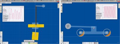
Strange program this Algodoo, it looks so childish and friendly that is frustrating to realize of not having the skills of a 4-12 child. However it is enough to see a single demo to understand that behind there is a huge computing power, that takes into account lots of parameters: frictions, elasticity, fluidity, inertia, accelerations and so on.
So i've tried with effort to dimension my parts through lots of menu, and to skip the 2D limitations. Seems ok to see more or less what happens, less to get useful data. Imho.
After complaints here the first results (attachments):
Swinging CW #3046 3049- the idea surprisingly seems to work. It does not at 0 gravity because the frictions (even that of the air) slowly move everything, but it is enough to use a hundredth of the gravity (in practice a seismic pendulum with inclination <1°) to get the system remaining consistent over time.
Working also in our real wold? It would be useful, with those bulky carriages seen around...
Silicone damped wheels #3040- fairly useless simulation because the viscosity of the liquid is not settable (only indirectly, by changing the gravity input, but it's not the same). However it shows that the motion is more or less what imagined, and the effect really acting. But calibrating in practice the weight and viscosity of the silicone to get the right synchrony seems highly difficult to achieve
have fun - carlo
Attachments
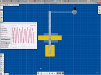
Algadoo seems made to simulate trucks o buildings, less common objects, but zooming to maximum finally i made something nearer to a real tonearm, with measures in gr and cm. (attachments)
Better, now the center of mass lays where it has to be, and the behavior seems more than acceptable.
So, sooner or later a proto like this, with a fine tuning seismic pendulum (attachment) has to be tried.
Will it work? with some sound improvement? it must be built to know...
carlo
sorry i can't find how to convert the simulation to mp4, so you have to install (for free) algadoo to play with
Attachments

Progress- of sorts
Hi all,
Kicking this thread up...
It has been a while since my last post on this thread....
Working slowly, but diligently, now the whole TT has a shape
Attached a few mock ups of the “arm”
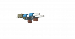
Recap:
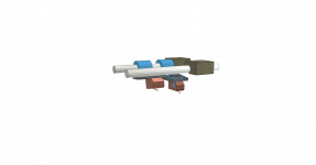
Active tonearm, the blocks push the semicylinder with the shell along the record- are not connected to the “hinge”
The hinge- semicylinder is the TA bearing, Igus, can cut the middle piece out, to reduce drag
Length center of axle to stylus - 40 mm
Eff mass: too low probably, but laboratory weights can be added to the shell
Vertical movement- almost none- the record is sucked down with a vacu mat+Center reflex clamp
Suggestions, issues, show stoppers- let me have em
Best,
Coolerooney
Hi all,
Kicking this thread up...
It has been a while since my last post on this thread....
Working slowly, but diligently, now the whole TT has a shape
Attached a few mock ups of the “arm”
Recap:
Active tonearm, the blocks push the semicylinder with the shell along the record- are not connected to the “hinge”
The hinge- semicylinder is the TA bearing, Igus, can cut the middle piece out, to reduce drag
Length center of axle to stylus - 40 mm
Eff mass: too low probably, but laboratory weights can be added to the shell
Vertical movement- almost none- the record is sucked down with a vacu mat+Center reflex clamp
Suggestions, issues, show stoppers- let me have em
Best,
Coolerooney
Attachments
Last edited:
hi Coolerooney, glad to see you are still working on your project.
I can't understand two things of the 3d model.
what's the role of the rod + block above the cartridge?
if the block pushes the carriage, what happens when the carriage has to go back on eccentricity? being not connected it doesn't pull it?
ciao Carlo
I can't understand two things of the 3d model.
what's the role of the rod + block above the cartridge?
if the block pushes the carriage, what happens when the carriage has to go back on eccentricity? being not connected it doesn't pull it?
ciao Carlo
Hi Carlo
The rods are the rails that guide the whole TA, they stretch for about 40 cm to the other side of the platter
The square blocks are connected to each other (not shown) and a threaded spindle drives it to the end
Eccentricty is an issue-considering preprocessing the record-bit of a hassle- or using the housing of the TA to do the pull back
Best
Coolerooney
Thxs, I got it: two blocks, two rods.
No warps, no eccentricity are a good thing for sure. Just a bit of a hassle, as you say.
Keep us informed
carlo
No warps, no eccentricity are a good thing for sure. Just a bit of a hassle, as you say.
Keep us informed
carlo
Another DIY LT Arm joins the fold
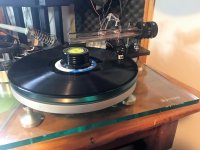
This one is built on a Michell Syncro
Still in prototyping phase but is sounding fantastic
Only one issue for which I need some advice.
The best sound and tracking is obtained with a VTF of ~3.8g
This seems way too high 😱, but it tracks beautifully, the sound stage is wide open, treble response is clear and pure, and no audible compression in the bass response. Also, with this tracking force the clicks and pops in the groove just disappear.
Please share your thoughts on this issue
This one is built on a Michell Syncro
Still in prototyping phase but is sounding fantastic
- 2 x 10mm OD tubes for the rails
- 10mmOD/5mmID/4mmW bearings
- ~ 75mm from pivot point to stylus tip
- Mounted in 30mm acrylic tube
Only one issue for which I need some advice.
The best sound and tracking is obtained with a VTF of ~3.8g
This seems way too high 😱, but it tracks beautifully, the sound stage is wide open, treble response is clear and pure, and no audible compression in the bass response. Also, with this tracking force the clicks and pops in the groove just disappear.
Please share your thoughts on this issue
Attachments
Waiting for authoritative advices, just some common tips from a diyer
- VTF 3.8: you mean that tracks better with it, or that it's needed to track? in this case two first areas of intervention:
- Cables: plastic-coated are always too rigid, use instead < 0.15 enameled ones. Someone suggests to avoid pair twisting, but keep care of possible humming. Even their shape is crucial, a big loop is often used to get them rotating, instead of bending
- Carriage: Niffy invented a simple reversed pendulum to measure its friction (I made a rougher version, see #2574-2605). If > 0.200 gr you're in trouble. For this try the usual solutions - in order of efficiency: better bearings (...much better, from de-greasing, to non recirculating ones, up to jewels) shorter wand, weight reduction. In my opinion if the bearings rotate properly there is no relative movement between the wheels and rails, and therefore material's friction is not so important. The vertical movement due ball bearings sliding may bring some offset bearing load (now minimizing that friction becomes crucial)
- Sound: more than listening, it is important to look carefully at cantilever behavior (bending), especially on LP defects.
Meanwhile my compliments for your beautiful proto - carlo
For me a "different" sound is a symptom of problems, not of solutions, and with such VTF seems difficult to judge, isn't it?
Nocdplz
Thanks for the compliment & advice
Yes, VTF 3.8g is needed for it to track
I think I know the reason now.
I bought a cheap (trade in) cartridge from my local hifi store to set this up.
Turns out it is an AT 3600L cartridge, which has a 0.6mm spherical tip and a tracking force range of 3-4 grams
Seems it is behaving, just as it should (where is that face palm icon?)
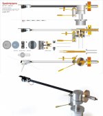
Hi everyone.
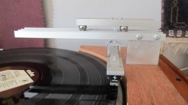
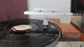
Here is my take on a linear tracker.
Actually I was very inspired by the Li'l Casey and wanted to make that, but as you can see, my mechanical skills (as well as my tools) really are very limited, so I dropped that idea.
This is a work in progress and more a proof of concept than a working tonearm, but it works perfectly well, with no skipping at all.
This has been made before, but not, if I recall correctly, with a Knife Edge bearing as the vertical bearing, and not with the support going directly from the horizontal bearing as in the Li'l Casey design. The other arms have all had a rather big structure going around the horizontal bearing. The knife in the vertical bearing is made from a Stanley Knife blade.
I am going to make a much shorter version of the arm that holds the Knife edge bearing, it is much too long now.
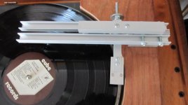
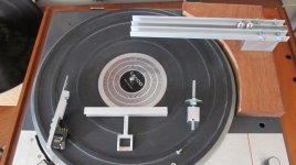
The ends of the two U-profiles ,that forms the track for the balls , need to be linked together for better stability, but this has to wait, as I am working on an automatic sledge that follows the arm to carry the wires from the tonearm, in order to reduce the drag from them.
I have already made a working motor-lift so the hole arm will be automatic, though still completely passive at the same time.
More will follow.
Comments , positive or negative, are very welcome.
Here is my take on a linear tracker.
Actually I was very inspired by the Li'l Casey and wanted to make that, but as you can see, my mechanical skills (as well as my tools) really are very limited, so I dropped that idea.
This is a work in progress and more a proof of concept than a working tonearm, but it works perfectly well, with no skipping at all.
This has been made before, but not, if I recall correctly, with a Knife Edge bearing as the vertical bearing, and not with the support going directly from the horizontal bearing as in the Li'l Casey design. The other arms have all had a rather big structure going around the horizontal bearing. The knife in the vertical bearing is made from a Stanley Knife blade.
I am going to make a much shorter version of the arm that holds the Knife edge bearing, it is much too long now.
The ends of the two U-profiles ,that forms the track for the balls , need to be linked together for better stability, but this has to wait, as I am working on an automatic sledge that follows the arm to carry the wires from the tonearm, in order to reduce the drag from them.
I have already made a working motor-lift so the hole arm will be automatic, though still completely passive at the same time.
More will follow.
Comments , positive or negative, are very welcome.
Attachments
Hi everyone.
Here is my take on a linear tracker.
Actually I was very inspired by the Li'l Casey and wanted to make that, but as you can see, my mechanical skills (as well as my tools) really are very limited, so I dropped that idea.
This is a work in progress and more a proof of concept than a working tonearm, but it works perfectly well, with no skipping at all.
This has been made before, but not, if I recall correctly, with a Knife Edge bearing as the vertical bearing, and not with the support going directly from the horizontal bearing as in the Li'l Casey design. The other arms have all had a rather big structure going around the horizontal bearing. The knife in the vertical bearing is made from a Stanley Knife blade.
I am going to make a much shorter version of the arm that holds the Knife edge bearing, it is much too long now.
The ends of the two U-profiles ,that forms the track for the balls , need to be linked together for better stability, but this has to wait, as I am working on an automatic sledge that follows the arm to carry the wires from the tonearm, in order to reduce the drag from them.
I have already made a working motor-lift so the hole arm will be automatic, though still completely passive at the same time.
More will follow.
Comments , positive or negative, are very welcome.
That’s pretty cool. Good luck
Hi Koldby,
It's great to see someone developing new ideas and experimenting with different concepts.
A very similar arm to yours was developed in this thread
My Linear Tracker (a new variation perhaps?)
I think that the version developed here has a couple of advantages.
First off. With your version it is possible for the arm to rotate about both the knife edge due to height variation and about the balls due to drag, this could cause the upper part of the carriage to swing inperceptibly forwards. With the arm by soyuz both the vertical and lateral pivots are catered for by the balls and should be more stable. Both arm designs have a low vertical pivot which is a good idea.
By making the carriage as a single component rather than an articulated pair the overall rigidity can be made much greater. You only have a certain amount of mass that you can use for the whole carriage. You want to use all of it where it will aid rigidity.
Soyuz's arm uses round tubes rather than U sections. This will allow the use of much harder and smoother materials (at least for the fixed rails) such as borosilicate glass or tungsten carbide. This will help to reduce lateral friction. Generally, the harder and smoother the materials used in bearings the lower the friction. You could also use ceramic balls to help further.
The amount of friction in the vertical plane can be reduced by using smaller balls and thinner rods/tubes. You don't necessarily want zero friction in the vertical plane. A little bit of friction can be useful as it will help to damp vertical motion.
I hope these comments are helpful.
Niffy
Thanks for the comments.Hi Koldby,
It's great to see someone developing new ideas and experimenting with different concepts.
A very similar arm to yours was developed in this thread
My Linear Tracker (a new variation perhaps?)
I think that the version developed here has a couple of advantages.
First off. With your version it is possible for the arm to rotate about both the knife edge due to height variation and about the balls due to drag, this could cause the upper part of the carriage to swing inperceptibly forwards. With the arm by soyuz both the vertical and lateral pivots are catered for by the balls and should be more stable. Both arm designs have a low vertical pivot which is a good idea.
By making the carriage as a single component rather than an articulated pair the overall rigidity can be made much greater. You only have a certain amount of mass that you can use for the whole carriage. You want to use all of it where it will aid rigidity.
Soyuz's arm uses round tubes rather than U sections. This will allow the use of much harder and smoother materials (at least for the fixed rails) such as borosilicate glass or tungsten carbide. This will help to reduce lateral friction. Generally, the harder and smoother the materials used in bearings the lower the friction. You could also use ceramic balls to help further.
The amount of friction in the vertical plane can be reduced by using smaller balls and thinner rods/tubes. You don't necessarily want zero friction in the vertical plane. A little bit of friction can be useful as it will help to damp vertical motion.
I hope these comments are helpful.
Niffy
I was absolutely inspired by the arm you linked to, as was the Li'l Casey, and made several version of the bearing with Pyrex glass rods, but I didn't like the high position of the vertical bearing.
I was myself worried about the rotation at the balls instead of the knife edge bearing, but it dosen't happen. The alu piece that holds the knife edge is not moving at all in that direction only tangential to the record.
It also came as a surprise to me, given the soft nature of aluminium, that it worked so friction-free. I have made bearings with Pyrex glass and small ball-bearings and the friction here was much higher. I have also experimented with different sizes of balls, and my findings were that when I used bigger balls the bearing had less friction. Not at all a scientific test, though, and it might have something to do with the weight of the balls, but the hole arm with the big balls is almost as difficult to level so the arm dosen't move, as an air bearing arm, and this is not the case with small balls.
Ultimately I also think that I should glue some Pyrex glass rods inside the U - profiles so the balls rest on them instead of the alu sides. Perhaps also some small rods in the u- profile on top of the balls. The weight here dosent matter so much, because it only affects the horizontal mass and not the vertical, because of the knife edge bearing, another of the advantages using a seperate bearing for the vertical movement. IMHO..😉
Last edited:
Interesting realization, Koldby- congratulations. I'm pleased that Lil Casey drove you to build a linear TA, using the non-recirculating bearing, which in my opinion is much simpler and more effective than the ball bearings solutions. Non recirculating bearings are around since a long time before the pyramids, and i've used because of their light weight and compactness. (tested before on Syrinx PLT)
But consider that the only basic idea of Lil Casey is just the radial rail, directly superimposed on the stylus tip (# 2355). The kind of bearings, and even the parallelogram, are just building details.
Seen your realization, you're certainly able to build a radial rail TA: if you want to avoid the parallelogram for the vertical articulation, which requires a certain precision (but not a lathe or mill), please look at post # 2383: that prototype, a typical "kitchen table TA", already worked flawlessly.
I believe that realizing something like, with great care to the weights we can obtain an excellent TA, not inferior to those with the parallelogram. (except for aesthetic and comfort, maybe)
ciao- carlo
p.s -What you say about friction may be explained in two ways: A - aluminum anodization hardness is 8-9 Mohs, near the top of the list - B there is (almost) no sliding between balls and rail, so the friction has (almost) no relation with their material.
Last edited:
koldby,
What are the size of the bearing balls? They look like they could be from a pinball machine?
Thanks!
What are the size of the bearing balls? They look like they could be from a pinball machine?
Thanks!
The balls are 12,7 mm.koldby,
What are the size of the bearing balls? They look like they could be from a pinball machine?
Thanks!
I got them from a company that has balls of steel (sorry --- I couldn't resist that 😛) in many different sizes, so I too now, have balls of steel ( uups--- once again 😱 )in many different sizes ...
Hi Koldby,
Looks like you've already covered all the points I made. Larger balls should, and do, reduce rolling resistance. Looking forward to seeing how you develop your arm.
Niffy
Looks like you've already covered all the points I made. Larger balls should, and do, reduce rolling resistance. Looking forward to seeing how you develop your arm.
Niffy
Carlo:
I know my design violates the main principle of the Lil Casey, and I am quite sure the direct coupling to the radial rail is better, just as Niffy pointed out in his comment. I thought the low placement of the vertical bearing and the low active vertical mass (potentially) could be beneficial and at the same time easier to make. I have been looking at the design in #2383 , but thought it was too massive and probably too high mass. A thought concerning that: Could it be made so the pivot is only about 50 mm from the radial rail, but made so long so it is supported both right AND left side of the table? Wouldn't it reduce the moving mass and make it much more rigid.
Niffy:
Not covered all the points , but I had given them thought. Unfortunately, the arm, as it is now, did not pass the acid test: A Shure M44MG (pretty high compliance 25um/mN) mounted in the arm and inspected closely with a magnifying glass, showed lateral movement of the cantilever and some times pretty abrupt movement back to neutral position. This indicates for me that the stiction is too high in this design, so you were probably right, pointing out, that the U-profiles either is not hard enough or (maybe more likely) the extrusion is not precisely enough so the surface (or edge) is not smooth enough. The anodization is hard, as Carlo points out, but it is very thin, so maybe it can easily get small dips or valleys pressed in?.
I am back to the drawing board, and will report shortly.
Carlo:
The design in #2383:
Another way to make it is to use a supporting structure like Niffy's arm (big and sturdy) and the pivot placed about 50 mm left and 50 mm behind the center spindle and use the Lil Casey type of radial rail. The moving mass would be less than in Lil Casey , wouldn't it?
And the vertical bearing could be my beloved knife edge (easy to make and here they only have horizontal force on them , right?)
- Home
- Source & Line
- Analogue Source
- DIY linear tonearm