Incablock - sorry, I was wrong: it also uses hole jewel+endstone. My memory associated the springed shock proof mechanism to a vee bearing
carlo
carlo
Hi Carlo,
You can get spring loaded vees but they aren't advantageous in this application. My vees are set into the ends of M3 threaded aluminium mounts. The mounts are locked in place by an M3 grub screw. When adjusting the bearings I slacken one of the locking grub screw so that the mount will only just turn. This is to prevent any play in the mount when adjusting. I then screw in this mount until the vee just contacts the pivot. At this point there will be no play (end-shake). I then slacken off the mount by undoing it by 2-3°. Adjusting by such a small angle is not easy so can take a good number of attempts to get just right. When you do get it spot on the bearing runs really smoothly with no discernable play. As an M3 thread has a pitch of 0.5mm a 2-3° adjustment with move the mount by 3-4.5um.
Niffy
No springs? interesting and surprising too, since screws have always some backlash; so it's difficult to imagine how to deal with such kind of clearance (3-5 um !) in a contact-no-contact situation.
Wouldn't be better to use a 3 mm fine pitch (0,35) screw? a 5° turn seems easier to achieve, and less backlash as bonus.
c
Wouldn't be better to use a 3 mm fine pitch (0,35) screw? a 5° turn seems easier to achieve, and less backlash as bonus.
c
Hi Niffy,
I can see the merits of the vee jewel now.Watches need to have jewels that work in different directions and are constantly moving relatively fast especially the balance wheel.
Its made me realise though how critical setup is of vee jewel without spring.
I can see the merits of the vee jewel now.Watches need to have jewels that work in different directions and are constantly moving relatively fast especially the balance wheel.
Its made me realise though how critical setup is of vee jewel without spring.
Hi Carlo,
As long as all the screws are adjusted and left with the backlash on the inward turn of the M3 thread then the clearance will not open up further. In other words if you screw the adjuster out then screw it back in to take up the backlash. Easier said than done maybe with such small turns.
Chris vee jewels are used in high quality mechanical instruments, all of my dial indicators use vee jewel movements. I have also repaired test gauges that used vee jewel movements and these do not have sprung pivots. Dropping them makes them unuseable.
Wow, Good job, and amazing! How you compare your glass rail to a linear ball bearing? Friction is what we see an issue on tone arm movements. I once had the impulse of making one, but gave up. Not being a workshop, I don't have the materials or the things I wanted out from a lathe or milling mc. But all projects are all very intersting.
Last edited:
Hi Warrjon
Comes to mind what happens with the lathe's carriage: as long as you keep moving forward, you keep the measurements, if you go back and then forward again you've lost it.
So I wonder how to get such micro tolerances, especially considering the stiffness of the pivot and the jewel: hence my surprise.
carlo
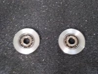
I made these today from 316 stainless bar. The wheels are 16mm in diameter and 4mm wide. They did make a difference, the XSV now tracks without miss tracking but the cantilever is still moving back and forth not the tonearm.
The other device is my alignment jig. The XSV stylus is impossible to see when aligning this makes it easy.
Before the wheel upgrade. You can see the arm jumping to the left.
YouTube
.
The other device is my alignment jig. The XSV stylus is impossible to see when aligning this makes it easy.
Before the wheel upgrade. You can see the arm jumping to the left.
YouTube
.
Attachments
No springs? interesting and surprising too, since screws have always some backlash; so it's difficult to imagine how to deal with such kind of clearance (3-5 um !) in a contact-no-contact situation.
Wouldn't be better to use a 3 mm fine pitch (0,35) screw? a 5° turn seems easier to achieve, and less backlash as bonus.
c
By keeping the locking grub screw quite tight the thread of the mount is pushed sideways into the thread of hole. This seems to eradicate the problem of backlash.
Niffy
Clever, Niffy! let me understand, you have a side screw braking the tuning one, instead of the usual lock nut on it? Acting on a slick section of it, I may imagine: now even a 2° rotation seems more feasible-
c
c
Exactly. The side locking grub screw also gets rid of a couple of problems that a locking nut has. When tightening a lock nut the mount will have a tendency to want to turn with the locking nut which will alter the setting making fine adjustments very difficult. A locking nut works by putting the material of the mount into compression. This could pull the mount out of position as any slack in the thread is taken up. As I'm attempting to get the bearing set to within a couple of microns any movement is undesirable.
Niffy
Niffy
Sorry, that should have been "A locking nut works by putting the material of the mount under tension."
Niffy
Niffy
Got it working with the Pickering.
I increased the radius on the edge of the wheels and polished them down to 1000grit. Then added the brush.
It tracks much better now. I did a back to back with the Technics EPA-100 with the same stylus in 2 different cartridges, these cartridges are so close channel balance is withing 0.1dB. WOW the difference is not subtle, the linear arm murdered the EPA-100 in both detail and bass punch.
.
Congratulations on the brilliant result, warrjon. And more, from turner to turner, for the nice stainless wheels: still remembering the screeching of a brazed tool on the 316 ... before breaking.
carlo
carlo
I use carbide insert tooling mostly. HSS is used for aluminium as it's sharper than carbide.
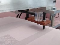
Good old fashioned Pommy lathe. Great tool.
Stainless work hardens so need to keep it cool. I don't use flood coolant as the pump in my lathe is shot I use coolant in a spray bottle
Good old fashioned Pommy lathe. Great tool.
Stainless work hardens so need to keep it cool. I don't use flood coolant as the pump in my lathe is shot I use coolant in a spray bottle
Attachments

Hi Warrjon,
Great news about getting your arm singing.
With both the wheels and rails of my arm I polished the surfaces with diamond paste, gradually working my way down to 0.5um. This gives a much smoother finish than you will get from 1000grit paper and has a quite noticeable effect on the rolling resistance of the bearings. When you get the tungsten carbide rods and rings I would definitely recommend spending a bit of time polishing to the highest finish you can.
Niffy
Hi Niffy,
I have ordered diamond lapping paste in 7 grits to 0.25um. I am going to make another set of wheels and polish them further. Dam the carbide rods turned up and they sent 100mm instead of 200mm, oh well waiting again.
This is a seriously good arm now, can't wait to hear the next iteration.
I have ordered diamond lapping paste in 7 grits to 0.25um. I am going to make another set of wheels and polish them further. Dam the carbide rods turned up and they sent 100mm instead of 200mm, oh well waiting again.
This is a seriously good arm now, can't wait to hear the next iteration.
I started with 1200grit wet and dry which I used until the rods had a uniform fine finish. Then I moved onto the diamond paste starting with 15um and worked through about 7 grades to end up at 0.5um. I applied the paste using pieces of soft fine grain leather. I used a combination of spinning the carbide rods in my pillar drill whilst moving the leather pad up and down slowly and having the drill stopped and working up and down more rapidly. It took 4-5 hours to get the rods to their final finish.
The parking location for the carriage, where it remains secure when changing records, has the right hand wheel run off the end of the rods and into a dip. So that the transition is smooth the ends of the rods are rounded and polished.
Niffy
The parking location for the carriage, where it remains secure when changing records, has the right hand wheel run off the end of the rods and into a dip. So that the transition is smooth the ends of the rods are rounded and polished.
Niffy
Knowing so little, I tend to believe in simplistic explanations: but won't it be that, more than for the Hertzian stress, the advantage of larger wheels is mainly to provide a greater torque to overcome the friction of the ball bearings? more or less the principle that led to discover the pin bearings...
carlo
Beautiful, rock solid lathe, Warrjon, especially compared with my poor chinese 9x20.
carlo
Beautiful, rock solid lathe, Warrjon, especially compared with my poor chinese 9x20.
Last edited:
- Home
- Source & Line
- Analogue Source
- DIY linear tonearm