Hello Chris in Brighton,
The welding rods I remember, are about 1/8" in diameter, which, in my opinion, is too small. If you're on a tight budget, you could inlay them into a groove machined into a larger diameter rod of a softer material like brass.
You might be able to polish them with diamond paper whilst remembering that you only have to polish a narrow band where the carriage bearings contact the rod.
The tool marks left after polishing should align with the longitudinal dimension of the rod, also called "lay"
Sincerely,
Ralf
Hi,they are commonly available in 2.4mm and 3.2mm.but are often in just 150mm lengths.Also they are pure tungsten not carbide if that makes a difference.
Very cheap though!
Very cheap though!
Well tungsten is a metal and tungsten carbide is a ceramic (though typically embedded in cobalt), so definitely different. Tungsten carbide is much harder than any metal, for instance, but more brittle (which is why its used embedded in cobalt for cutting tools).
I paid $36AUD for 2x 4x200mm carbide rods from eBay. That's about 19 quid.
150mm length is a bit too short you need 200mm to give room for parking the arm off the record surface, and you have the width of the carriage between the roller to take into account.
150mm length is a bit too short you need 200mm to give room for parking the arm off the record surface, and you have the width of the carriage between the roller to take into account.
Hi Chris,
As Mark pointed out metallic tungsten and tungsten carbide are very different with carbide being much harder. The advantage of metallic tungsten welding rods is that they are much cheaper. When I was developing my bearing system I used borosilicate glass rods and made several different rails for use with different bearing types until I found the option that worked best for me then remade that rail with tungsten carbide. You could do a similar thing and use the metallic tungsten for prototyping and then use carbide for the final version. Or you might just decide to stick with metallic tungsten as it will probably still be really good. I would probably have stuck with glass if Joe hadn't introduced me to carbide. The sound I was getting with stainless steel wheels on glass with homemade steel pin bearings was really good. Upgrading to carbide rails and wheels with sapphire and carbide pin bearings did result in a significant improvement in sound quality. It is also a vastly more expensive option, costing well over £200 more than the steel and glass version.
When it comes to the diameter of the rods there are a couple of points to take into account. Between the two rods forms a curved V in which the wheels run. If you have large diameter rods and narrow wheels the wheels will sit very deep in the V and the contact angle between the wheel and the rail will be high. If on the other hand you have smaller diameter rods and wider wheels the contact angle will be lower. Ideally you want the contact angle to be in the 20-30° range. When I was using ballrace bearings I used 4mm glass rods and 4mm wide bearings. I used a 1.5mm carbon fibre spacer between the rods which resulted in a contact angle of 22°. With my current set up I have 2mm wide wheels running on 4mm rods with no spacer given a contact angle of 30°.
The advantage of using a smaller diameter rod (with a spacer if necessary) is that the vertical pivot can be made to be closer to the record surface reducing the likelihood of warp wow. It also gives greater flexibility in the design of the rail.
Using smaller diameter rods and correspondingly thinner wheels (so the contact angle remains the same) should not effect lateral tracking friction. It will, however, reduce vertical friction. With my arm I chose 4mm rods with 2mm wheels so that the vertical friction would act to damp the oscillation of arm due to the effective mass/compliance resonance.
It would be interesting to try my arm with 3mm rods and wheels only 1.5mm thick. This would slightly lower the vertical pivot point and reduce vertical friction but would also reduce vertical damping. On balance I think the 4mm rods are probably going to be better than 3mm but probably not by enough to be significant.
I lived in Brighton for 9 years. You are blessed with the best record shop in the UK (maybe the world). Anyone who visits Brighton owes it to themselves to visit Resident records in Kensington Gardens.
about us - resident
Niffy
Thanks for the advice,i hadnt realised tig tungsten was softer!and also couldn`t find any tig electrodes longer than 150mm anyway.
After trawling the net i ended up finding carbide rods in a range of diameters 300mm long from my usual source for drill bits-msc supplies.
Im alright for jewelled bearings but finding carbide rings in small sizes is proving more a challenge.
Yes we are spoilt for choice in Brighton for record shops!
Hi Niffy,
Quick question, when you made your SS pin bearing wheels what radius did you put on the edge of the wheel? I know was in here somewhere but 300 pages to go through!!
I mounted my Pickering XSV3000 (30um/nm compliance) and it will not track in this arm, it jerks and mis-tracks. I want to machine larger diameter wheels from SS I have in stock and reduce carriage weight.
cheers Warren
I am waiting for this, I ordered some time ago:
K10 Solid Cemented Carbide Tungsten Steel Round Bar Rods L: 10/20cm D: 2-10mm AU | eBay
K10 Solid Cemented Carbide Tungsten Steel Round Bar Rods L: 10/20cm D: 2-10mm AU | eBay
Hi Warrjon, Chris,
The stainless Steel wheels were made from 2mm plate. I made a couple of set of wheels, one with a 1mm edge radius so the edge was completely rounded over and one set that were almost square edged with a radius of about 0.15mm. The wheels that sounded the best were the one's with the 0.15mm radius. This was a bit of a surprise as I had thought that the fully rounded edges would be a better option. The measured lateral friction of the two profiles was identical. If I remember correctly the vertical friction of the wheels with the 0.15mm radius was very slightly higher. This small increase in friction would damp the vertical motion of the arm a little bit more. This might partially explain the difference in sound. I think the main difference is that the 0.15mm radius wheels will have a smaller contact point with the rail with a correspondingly higher contact pressure. This could result in better mechanical grounding. The difference in sound was very subtle. The 0.15mm radius wheels seemed to define the edges of notes a little better and sounded a bit cleaner.
In my final version of the wheels I used 2mm wide tungsten carbide wedding rings. These are available as either dome, which is fully rounded, or plain that is basically square with a small edge radius. I used the plain.
I had quick look on eBay and found these at a fiver each.
2MM Tungsten Carbide Stackable Ring Plain Wedding Band | eBay
Size I has an id of about 15mm so the od will be about 18mm. This is a bit larger than the ones that I used but I was fitting them in an existing carriage and was tight on space.
The disadvantages of a larger diameter ring is that it will weigh more and its centre of mass will be higher.
The advantages of a larger diameter ring is that rolling resistance will be lower and as the bearing has to rotate through a smaller angle for the same linear displacement the bearing friction will be lower. Plus the larger radius acts like a longer lever. This means that linear friction should be lower. Vertical friction will not be significantly effected.
Niffy
Cheers Niffy,
I bought a pair of those rings a week ago from that seller.
My arm does not move back and forward you can see the stylus moving, it jerks across so lateral friction is way too high. I am using SS/ceramic ABEC9 hybrid bearings from BOCA they are dry lube and for an Abu Garcia fishing reel.
I have some 20mm 316 stainless bar I am going to make rings for an aluminium disc with the bearing pressed into the aluminium. this is a makeshift until I get my new TT1 style arm built. I might even oil harden the ring.
.
Hi Warrjon,
Those rings will be perfect with the 4mm rods you bought from Australia. 200mm is a good length. My rail is 190mm long so the stylus is only about 10mm clear of the edge of the platter when the arm is parked. 10mm if fine for me but I imagine most people would prefer a little more clearance.
Could you please clarify what you are doing with the 316 steel and aluminium. I got a bit lost. Are you making temporary wheels with steel rims and saving the tungsten carbide for your final version?
Niffy
Could you please clarify what you are doing with the 316 steel and aluminium. I got a bit lost. Are you making temporary wheels with steel rims and saving the tungsten carbide for your final version?
Niffy
Hi Nifty,
Basically yes, the tungsten rings are coming from China so could take a month or more.
I'm going to press the bearings into the aluminium then press the aluminium wheel into the 316 rings. Then machine the outer rings concentric to the bearings. I'll drop the thickness to 3mm which will give me 30deg on the 6mm glass rods on my current arm.
Living in a rural town I need to order everything online so I'm still waiting for materials to make the TT1 style arm.
The post is a bit slow at present. between fires and holidays.. I am Also waiting on the Postie.Living in a rural town I need to order everything online so I'm still waiting for materials to make the TT1 style arm.
I keep getting a bugging thought about the vee jewel bearings.I read the article about miniature ball races in clocks(few pages back) and understand that a tiny vee point will have less friction than the best ball race.
But as I come from experience with watch repairing I cant understand why watches never use vee jewels for their balances.instead they have very slim pivots and use combined pierced jewel and a flat endstone.It results in the pivot being quite fragile hence why shockproof jewels were invented.
Im worried that a vee jewel with any slack at all will shake,and without slack will be tight.
maybe in the real world they work fine?
I was reading this article.
Plant Engineering | Calculating proper rolling resistance: A safer move for material handling
What was interesting was the "Major Factors in rolling resistance" bearing type was in the factors that can usually be ignored. So my plan is to use the ball race bearings I have and insert them into larger diameter aluminium wheels with stainless rings. Hopefully I should have them finished by Sunday so I can test them.
Hi Chris,
Fine adjustment of vee bearings is essential for optimal performance. You actually want a very small amount of clearance, I have somewhere in the region of 5um. Ironically, from the wording of your concern, this clearance is called end-shake. The load in our application is at 90° to the axis of the pivot so the contact points will always be under load. The spherical tip of the pivot still rests within the spherical portion of the vee. The contact point between the pivot and vee is very small. I did work it out for my arm but can't remember the exact size. We're talking a couple of microns in diameter. The contact pressure is immense, mega-pascals. There is nothing in the dynamic behaviour of the arm that is going to be able to cause the pivot to shake or vibrate against the vee.
I assume that your concern is with bearing wear. I have been running my arm for 3-4 years with the jeweled bearings and they haven't given me any cause for concern. My carriage, at 55g, is a lot heavier than most of the other carriages shown in this thread so my bearings are probably going to be more heavily loaded than yours. I also ran the stainless steel pin bearings for about 6 months before I moved to the jewels. I could not see any signs of wear or damage on these either.
I hope this helps to calm that bugging thought.
Niffy
I was reading this article.
Plant Engineering | Calculating proper rolling resistance: A safer move for material handling
What was interesting was the "Major Factors in rolling resistance" bearing type was in the factors that can usually be ignored. So my plan is to use the ball race bearings I have and insert them into larger diameter aluminium wheels with stainless rings. Hopefully I should have them finished by Sunday so I can test them.
Hi Warrjon,
The article pretty much sums up my findings.
It is difficult to quantify the exact proportion of the overall friction that is due to rolling resistance and that due to the bearing element. As I did many tests changing only one thing at a time I can estimate that about 80% of the overall friction of my bearings is rolling resistance. Compared to using the boca hybrid bearings my current level of lateral friction is about 1/4 that amount. This huge difference is due to refining both aspects.
Friction is not the only factor that is important.
If you use the ball race bearings as you suggest you could end up with a double vertical pivot. One pivot at the wheel/rail contact and one due to the play in the bearing. As the friction in the play of the bearing varies by a large amount the arm might sometimes pivot at one point and sometimes about the other. The first arm I built many years ago had a bearing in a wheel very much as you suggest. The vertical pivot was noticeably unstable. Having said that it still stuffed an SME V.
The level of friction from a ballrace, when operated at very low speed and in a stop/start manner, in not very consistent. The actual level of friction varies quite a lot.
You will still have the likelihood of chatter.
In my opinion the greatest impacts on sound quality when going from ballrace to pin bearings was the improvement in mechanical grounding (coupling) and the elimination of chatter. The reduction in lateral tracking error due to the reduction in friction played a much more minor role.
It's still definitely an experiment that's worth doing and will give you valuable information, good luck.
Niffy
Hi Niffy,
Good point about the two pivots, I hadn't thought about that I might leave the SS ring at 4mm width.
This is not so much an experiment as getting this version of the arm to work with my Pickering XSV3000. The XSV3000 sounds better in the EPA100 than the EPC205 in the linear. The EPC sounds better in the linear than the EPA , so if I can the XSV working in the linear it will be amazing. The lateral friction is way too high for the XSV the stylus is wandering back and forth with off centre pressing, the arm doesn't move back then it jerks and misstracks.
I will be using pin bearings when I make the TT1 arm.
I'm using an ortofon 2M black which is quite high compliance, 22um/mN. Even though my carriage is a bit heavier than most, which will result in higher friction, my cartridge runs perfectly with no deflection of the cantilever visible even under magnification. Although it is generally recommended to use medium to high compliance with a linear arm it is possible to design for high compliance.
The main effect of bearing friction in a linear arm will be increased lateral tracking error. Many moons ago I did a comparative investigation into different types of tonearm to see how they would compare in terms of LTA. I took absolutely everything that could have an effect into account. The results were based on a combination of direct measurements and mathematical analysis. I modeled all the different arm types as being perfectly set up with the 2M black cartridge. The lowest errors were achieved using a linear air bearing, the single largest contribution being due to inertia. My current arm came very close overall especially if the record was at all eccentric. It is likely that a very lightweight carriage using my bearings could have a lower average LTA error than an airbearing arm, again due to the lower inertia with eccentric records.
Don't read too much into this. Bearing friction is only one aspect of tonearm design. Although an air bearing has lower friction it doesn't have any mechanical grounding (coupling). Although a lightweight carriage will have lower friction it will be less rigid and more prone to resonance. It's all a balance of compromise.
Niffy
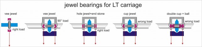
Chrisinbrighton on #3174 posted an very interesting question.
That jewel bearings are better than any other type for small loads, has been proven since the mid-eighteenth century (the famous Harrison H4 sea watch), with billions of watches produced. I don't know anything about watchmaking **, but maybe the reason why watches don't use vee jewels (the only one I know is the incablock) it's because they have to work in any position. To get very, very low friction a hole jewel + end stone can be not tight on the pivot, because it is enough not to exceed the needed tolerance of his gear.
While our tonearms hate chattering.
The only problem remains that the carriage loads the vee at 90 ° and therefore we need a spring to keep it aligned, certainly increasing somehow the load and friction. (see attachment).
Always less than that of a ball bearing, which however needs greater clearance to run freely and so on: hence all the problems Niffy had clearly described.
carlo
**as a sunday machinist I have just to envy the boundless ability of those who know how to make a pivot with a handheld graver on a watchmaker's lathe, or to work on tolerances i'm even unable to measure
Attachments
Last edited:
- Home
- Source & Line
- Analogue Source
- DIY linear tonearm