2019 last doubts
Since you're talking about, for me an opportunity to understand something more about LTs carriages (attachment).
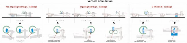
There's always a great research on materials with very high Mohs for the rail-to-bearing coupling. Why? in order to reduce wheels friction? But there is no (or should not be) relative surface motion. Isn't it better for a wheel to rotate, instead of sliding? Or this low friction is necessary to allow the vertical articulation, due some slipping? At first glance the V wheels solutions (like those beautifully created by Niffy) seem to me the only correct. What i'm missing?
Another doubt - some linear trackers exhibit very massive headshells, or even weights above the cartridge, often together with tiny CWs placed very far from the pivot. Why? to increase the vertical mass? usually we look for the opposite.
Thanks in advance - carlo
Deliberately left out the stylus-pivot-CW alignment problem
Since you're talking about, for me an opportunity to understand something more about LTs carriages (attachment).
There's always a great research on materials with very high Mohs for the rail-to-bearing coupling. Why? in order to reduce wheels friction? But there is no (or should not be) relative surface motion. Isn't it better for a wheel to rotate, instead of sliding? Or this low friction is necessary to allow the vertical articulation, due some slipping? At first glance the V wheels solutions (like those beautifully created by Niffy) seem to me the only correct. What i'm missing?
Another doubt - some linear trackers exhibit very massive headshells, or even weights above the cartridge, often together with tiny CWs placed very far from the pivot. Why? to increase the vertical mass? usually we look for the opposite.
Thanks in advance - carlo
Deliberately left out the stylus-pivot-CW alignment problem
Attachments
Last edited:
Hi Carlo,
The reason for using very hard materials for the rails and wheels is not to reduce friction at the contact point. As you correctly point out there should be no relative surface motion. For lateral motion the coefficient of friction is irrelevant. What is important is rolling resistance. Very hard materials will have lower rolling resistance than softer materials. A good analogy, for anyone who has ever ridden a push bike, is the difference in how easy it is to cycle when the tyres are pumped up really hard compared to when the tyres are almost flat. It is much easier to cycle with the hard tyres. Similarly it is much easier to cycle on tarmac than grass. When cycling with hard tyres on tarmac you will have the lowest rolling resistance but the friction between the road and the tyre is still very high.
You might think that the difference in rolling resistance between steel running on borosilicate glass and tungsten carbide on tungsten carbide would be slight as both steel and glass are good and hard anyway. My measurements would indicate that the rolling resistance of steel on glass is 40% greater than for tc on tc. That extra bit of hardness actually makes a lot of difference.
Having a harder contact point also seems to improve mechanical grounding and has a definite positive effect on sound quality.
When it comes to vertical articulation of the arm the situation is a bit different. From your diagrams I assume that you are referring to the use of ball race bearings. With ball race bearings the vertical motion is not accommodated by the bearings sliding on the rails except when the vertical movement is large like when queuing or navigating a particularly severe warp. In normal operation the entire vertical movement is taken up by the play in the bearing. For the case of large warps where the play in the bearing is insufficient the sliding could be beneficial as this friction will act to damp the motion of the arm. With my pin bearing arm I actually use this sliding friction to specifically damp the arm.
Regarding your final doubt. The block type headshell, as used by clearaudio, is going to be more rigid and less prone to resonance than a thin flappy paddle type headshell as used in most arms and in this respect is a very good design choice. However making this type of headshell more massive is not the best way to increase vertical effective mass. It is much better to increase the effective mass by adding the extra mass where it will also increase rigidity, killing two birds with one stone. If you look at the pictures I recently posted of my lightweight carriage you'll see that I have used a block type headshell. You'll also notice that I have reduced its mass as much as possible by making it relatively thin ~5mm and by making it oval. The extra mass I required to get the best effective mass was obtained by making the front section of the armtube thicker walled. The exact effective mass was fine tuned by selecting the correct counterweight mass and distance from the pivot.
Niffy
Last edited:
Hi Niffy,
thanks for your accurate and effective answers: the example of the racing bike (5-6 Atm!) is particularly convincing for anyone who has ever used one. My doubt is that maybe with ball bearings commonly used for those arms, their inner friction plays a much greater role than the possible difference between normal and sophisticated materials of the rail. Much differently from your jewel bearings + minimal contact point.
The observation on small warps dealt with bearing's tolerances is also surely right, but does not reassure me, because even in this case there will be some pivot shifting to alter the behavior of the stylus (= colored sound). Worse, if this trend exists it will also appear with the instant variations of the stylus drag, like in suspended arms. Maybe with very good bearings the easier situation to happen could be that of (A) case. On a short 70 mm arm, an average 1.5mm warp generates an angle of 1.5°, enough to generate that kind of wobbling.
So, I still believe that your V wheels carriage is the only one that can be seriously used to achieve the vert. articulation.
When possible a solid head shell is certainly beneficial (but things seem more complicated, have you seen Korf's work?), however I have the strange feeling that the trivial reason for those weights is to keep the CW out of the perimeter of the disk, in order to reasonably lower the vertical pivot, together with the CG.
carlo
Hi Carlo,
You are quite correct. The overall lateral friction of the bearing is comprised of a combination of the rolling resistance and the friction due to the rotary bearing element. With a ball race bearing the majority of the friction is due to the bearing element. The friction of this element can be reduced by selecting bearings with the hardest components, ceramic or hybrid ceramic for instance. The use of any lubrication will cause the bearing to become 'sticky' which will increase friction.
The rolling resistance can be reduced further by polishing both the rail and the outer race of the bearing.
With the pin bearings I found that the majority of the friction is due to the rolling resistance even when using tungsten carbide wheels on tungsten carbide rails.
One of the major problems with ball race bearings is that their friction is not consistent. Ball race bearings are designed for high speed and high loads. We are using them at extremely low speed and loads. The level of friction varies dramatically depending upon the angle of rotation of the bearing. The bearings actually show bimodal levels of friction with the upper mode being about 50% higher than the main mode. The overall friction actually varies by much more than this. This variation is probably due to whether there is a ball at the bottom of the race or the gap between two balls. The variation in the friction of the play of the bearing, that allows for vertical articulation, varies by even more. About 700% if memory serves me well, again probably due to the position of the the balls. When used at high speed the variation in friction averages out to give smooth operation.
With the bearing system used by the lil casey there is no rotary element to the bearing. It still has two elements, both rolling resistance, one between the lower rail and ball and one between ball and upper rail. As with the other bearing types the overall friction will be mainly determined by the hardness of the rails and balls. The use of larger balls can also help to reduce lateral friction but will likely also increase vertical friction. Unfortunately harder materials, especially tungsten carbide, tend to have high density. A design like the lil casey requires that the rails and balls be as lightweight as possible. A compromise between overall mass and friction has to be made. The bearing system used by the lil casey will have several advantages over ball race bearings. The overall friction should be lower and much more consistent. There will be no bearing chatter. The loose/unloaded balls in a ball race are an uncontrolled source of chatter.
Niffy
Niffy, your analysis on ball bearings behavior should be put at the beginning of every thread on tonearms: there is a lot of confusion around. Difficult to mate the near zero friction with zero play, and high speed types - designed to work very hot - are not the right answer for our needs (especially for pivoted ones).
Frankly, still don't understand how builders can manage to make a LT with ball bearings work properly - I hadn't really succeeded, maybe they can get items inaccessible to mere mortals like me. Besides, the vertical articulation loads the bearings asymmetrically from the wrong side, with a chattering certainly greater than in the pivoted ones, where at least the lower balls remain under load.
This is why I had landed very soon on a non-recirculating balls system; the JR Casey #2360 behavior wasn't enough good but promising, and the proto of the Lil Casey #2383 - same bearing but without the negative lever of the shaft - worked perfectly from start.
As you say the non-recirculating balls have many advantages: great simplicity, no chattering, very low friction and, more, weights and dimensions that can be reduced to a minimum, as is indispensable on the Lil Casey. This naturally has a counterpart, because with small spheres the surface finish of the rails, even more than the hardness*, is of great importance.
And so for the dust on rails, that must be kept clean to avoid skipping. The tube protects, but I had to build a long brush to easily clean them every pair of months. For this reason the rail's end caps are tubular (lighter too)
carlo
* I did not measure particular differences using black delrin Harken balls, which sounded better on the first Lil Casey in anodized aluminum.
Last edited:
Hi Carlo,
When I initially built my carriage I designed it to use pin bearings. Unfortunately I had great difficulty building the wheels and bearings to a high enough standard, plus I made some poor choices of material. As I couldn't get the pin bearings to work I decided to resort to ballrace bearings so that I could finish building the deck. The plan being to revisit pin bearings a later date. Luckily it was very easy to fit an axle, for ballrace bearings, to the carriage.
I ran the arm with ballrace bearings for several years.
The sound quality that I achieved with ballraces was very good, better than any other arm I had heard, regardless of design. It is possible to achieve very high sound quality with ballrace bearings. Even though the sound of the arm was as good as it was I was still convinced that the bearings were the weak link, hence my investigation into bearing design. The move to pin bearings and exotic materials definitely elevated the sound a long way but the core sound was due to the overall design.
The first linear arm I built, about 25yrs ago, was made of aluminium and was similar in appearance to the lightweight arm I showed a couple of posts ago. I was fortunate enough to find myself with two identical high quality decks and two identical high end cartridges. One deck was set up with my arm and the other with an SME V. This allowed an easy A-B comparison. My basic arm easily bested the SME. This shows that a ballrace based arm can produce a high quality of sound.
When I first got the pin bearings working I was using borosilicate glass rods with stainless steel wheels. The next upgrade, after Joe very generously donated them, was to change to tungsten carbide rods. I was still using the same stainless wheels. The glass rods naturally have a very smooth surface. I polished the tungsten carbide rods to a half micron finish, very smooth but probably not quite as smooth as the glass. Moving from the glass to the polished tungsten carbide resulted in a reduction in lateral friction of 18%. When I received the tungsten carbide rods they had a much rougher surface, about the same as if they had been finished with 600 grit wet and dry. This is still a reasonably smooth finish. On Joe's request I tested the friction of the rods before polishing them. Polishing the rods resulted in a reduction in lateral friction of just under 7%. This test would suggest that hardness makes more difference than surface finish. As the test involves only two materials and two finishes the exact relationship cannot be determined. Combining hardness with a fine finish is of course the best option.
The vertical friction of the bearings with polished tungsten carbide rods was about 10% lower than when using the glass rods. With the addition of the tungsten carbide wheels the vertical friction fell by about another 20%. With the pin bearings the vertical motion is accommodated entirely by sliding on the rail and not by the play in the bearing.
Niffy
Certainly my patience and skill is far beneath, I would never be able to get a flat half micron finish (my attempts to make a decently lapped TT spindle on my lathe have always wrecked poorly).
Many years ago, my experiment with $KF bearings and a rectified HSS square (separate vert. articulation) showed such a scandalous stylus bending as to induce me to detest the linear trackers almost forever. However, it was a good lesson about bearings: for example that a couple, witn inner preloading, had less friction and chattering than one alone. Very useful to be applied to my previous gimbals, (and, more recently, also to the Birch - Rabbit, a textbook case of off-axis loads).
Recently found this
https://www.nskamericas.com/content/dam/nskcmsr/downloads/americas_bearing/e1254h.pdf (NSK seem very liberal with informations)
Hope may be useful for those who know as little as me, when choosing a proper bearing type for their different needs
Happy New Year to all - carlo
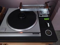
Finally installed the arm and aligned it with a USB microscope. Took a while to get rid of the hum. I ended up having to ground the SP10 chassis to the preamp ground. Now I have the grounding sorted I'll replace the alligator clips with spade connectors.
It sounds pretty good, bass response is better than my EPA100 although I have the EPC205 installed not the Stanton 881.
The only issue I have not sorted is the repeatability in VTF, this varies by 0.2g with multiple measurements.
It sounds pretty good, bass response is better than my EPA100 although I have the EPC205 installed not the Stanton 881.
The only issue I have not sorted is the repeatability in VTF, this varies by 0.2g with multiple measurements.
Attachments
Hi Warrjon,
Congratulations on getting your arm up and running, looking good.
Good bottom end is one of the defining characteristics of these linear arms. This is due to the high lateral effective mass that helps to control the lateral stability of the arm. Bass frequencies are cut laterally only with no vertical component.
The problem that you have with tracking force consistent is something that we all suffered when using ballrace bearings. This seems to be due largely to the inconsistencies in the bearings that I mentioned recently.
It is important that the surface of the pad of your scales is exactly level with the surface of the record. With most scales the measuring pad is much too high if the scale is set on the platter. . With your design of arm the scales will show a higher tracking force than you will actually get If the pad of the scales is too high.
I found that by repeatedly raising and lowering the stylus onto the scales the reading would settle down to a more consistent, but still quite varied, reading. I set tracking force as close as possible to the manufacturers recommendation using the scales then fine tuned by ear.
Happy New year.
Niffy
I removed the rubber mat and shimmed the scales to approx record height to set VTF.
I also found raising and lowering the the arm a few times the VTF settled.
I am planning to make a set of pin bearings and lower the rail to record height. This arm was a proof of concept to try against the EPA100 and it does out perform it in the bass. Next arm will be based on the Clear Audio TT1 it will be fixed at both sides and slide back.
Just need to find somewhere to buy the jewels.
Hi Warrjon,
The sonic advantages of placing the vertical pivot level with the surface of the record are not huge. The main advantage is that the arm is less likely to suffer from warp wow.
In order to lower the rail to record height will require the rail to be positioned past the edge of the platter. This will require that the arm has to be long, almost as long as a conventional pivoted arm. This will massively reduce the rigidity of the arm and increase its mass. The main advantage of the linear arm is not the reduction in lateral tracking error, this is just a bonus. The ability to utilise a short armtube is by far the main advantage of going linear.
If you are planning on making the arm slide back as with the TT1 you would be best to still have the rail above the platter but as low as possible.
As important as getting the vertical pivot close to the record surface is getting the center of mass close to the vertical pivot. This is done so that the tracking force doesn't vary as the height changes due to warps. With the rail located above the record is is relatively straightforward to get the center of mass level with the vertical pivot.
All of the negative effects of a short armtube can be reduced by using a warp flattening record clamp.
I purchased my sapphire vee bearings from a retailer on amazon. Unfortunately they no longer seem to be trading. I purchased the tungsten carbide pivots from true point audio in the UK.
True Point Audio
They aren't cheap but are very high quality.
Niffy
Hi Niffy,
That should have read just above record height. The arm will slide back on linear rails to facilitate record changing. My plan is to set COM to slightly below the vertical pivot. SME do this on the 309 and V this will have vtf increase slightly as the arm lifts.
Thanks for the link I had a look and they have Jewel V and tungsten pivots.
Here is an interesting read using ball race bearings in clocks. It also has info on friction tests. What was interesting for me was the difference between brass and jewel pivots.
Ball Bearings In Clocks by Boca Bearings :: Ceramic Bearing Specialists
Ball Bearings In Clocks by Boca Bearings :: Ceramic Bearing Specialists
Hi Warrjon,
Thanks for posting the link. Very interesting.
The use of the bearings in the linked investigation is quite different from what we are trying to achieve so the results are not going to be directly transferable. He was looking at just the rotation of the bearings whereas we are more interested in the overall lateral friction due to a combination of the bearing friction and rolling resistance. He was also normalising all of his results as if they were acting on a 2mm diameter shafts.
The type of jeweled bearing he tested is very different from the type that I am using. He was using a 1mm diameter olive with a steel shafts. This will result in the point of contact, where the friction occurs, to be 0.5mm from the axis of rotation. With a pin bearing the contact point is much closer to the axis of rotation, less than 0.05mm. As the load is the same and the coefficient of friction at the contact point is the same the sliding friction at the contact point will be the same. If you have the same frictional force acting at less than a tenth of the distance from the axis the resulting frictional torque will be less than a tenth as well. Actually the coefficient of friction between sapphire and tungsten carbide is lower than between sapphire and steel so the frictional torque will be lower again.
The velocity at the contact point with the pin bearings will also be less than a tenth of that seen with the olive bearing. This will result in the amount of energy being dissipated also being less than a tenth. Dissipated energy will be mainly in two forms, heat and vibration (noise).
The use of larger diameter wheels will also help reduce lateral friction as the applied force will be acting further from the axis so less force is required to overcome the frictional torque of the bearing. This is a similar concept to the friction wheel mentioned in the article. Larger wheels also have lower rolling resistance.
It would have been nice if he had included jewel vee bearings with tungsten carbide pivots as another type of jeweled bearing.
Niffy
Hi Niffy,
I stumbled across the site because I was researching materials to use as pivots. I am going to have a crack at making the pivot, brass Vee and tool steel pin, I have a handful of old ejector pins with 1/8 shafts.
I stumbled across the site because I was researching materials to use as pivots. I am going to have a crack at making the pivot, brass Vee and tool steel pin, I have a handful of old ejector pins with 1/8 shafts.
Hi Warrjon,
My first successful pin bearings used sewing pins with the ends rounded and polished as pivots and stainless Steel grub screws with the vee punched into one end. These worked much better than the best ball race bearings. The pivots had a tip radius of 0.125mm and the vees a radius of 0.25mm. Similar sizes to these should work with your brass and steel bearings.
The key to getting the bearings to work was in making a jig that centred the wheels with the bearings.
Niffy
Hi Warrjon,
My first successful pin bearings used sewing pins with the ends rounded and polished as pivots and stainless Steel grub screws with the vee punched into one end. These worked much better than the best ball race bearings. The pivots had a tip radius of 0.125mm and the vees a radius of 0.25mm. Similar sizes to these should work with your brass and steel bearings.
The key to getting the bearings to work was in making a jig that centred the wheels with the bearings.
Niffy
Thanks for the info.
I do have a home machine shop with Colchester lather and Bridgeport style milling machine so centering the pivots will be done on the lathe. I have thought about how I can make the vee. If I machine a pin with a 0.25 radius and harden it I can drill the brass vee and use the pin to polish the vee, then machine pins with 0.125 radius and harden the ends.
I'm still pondering whether the TT1 style or something more like the TT3 but modified to lower the rail height. The issue I see with a TT1 style unless I use solid aluminium ends is stability. It needs to hinge up or slide back. I am big on simplicity just need to think it through.
.
I'm still pondering whether the TT1 style or something more like the TT3 but modified to lower the rail height. The issue I see with a TT1 style unless I use solid aluminium ends is stability. It needs to hinge up or slide back. I am big on simplicity just need to think it through.
.
I also contemplated building my arm TT1 style. The advantage of having a support at either end of the rail is rigidity, a bridge is much more rigid than a cantilever. The disadvantages are that the sub-chassis will need to be larger in order to accommodate two mounting points. It also makes adjustment more difficult, you need to be able to adjust the hight and slope of the rail as well as lateral tracking. It is difficult to make these adjustments independent of each other with the TT1 style of arm. I ended up with a design that only mounts at one end but has a massive cantilevered structure that supports the rail from both ends. This makes for a very rigid structure with easy adjustability. Like the TT1 my arm slides to the rear for record changing. If you can design a working bridge type of mounting, similar to the TT1, it will probably be better than a cantilevered design.
Niffy
I have an SP10 so the plinth is quite large 500x400mm. I've built a mold to cast another plinth with the SP10 in the middle, this makes room to mount the arm either side of the TT. I have some ideas on how to make a bridge style easily adjustable.
I upgraded the bearings yesterday to the ABEC9 hybrid ceramic which made a noticeable improvement in detail.
I upgraded the bearings yesterday to the ABEC9 hybrid ceramic which made a noticeable improvement in detail.
tungsten rod
Hi,first post here but have read most of this thread!
I was looking into getting some tungsten rods and remembered i use them all the time for tig(gtaw) welding.
would these work? the surface finish may need alot of polishing.
Hi,first post here but have read most of this thread!
I was looking into getting some tungsten rods and remembered i use them all the time for tig(gtaw) welding.
would these work? the surface finish may need alot of polishing.
- Home
- Source & Line
- Analogue Source
- DIY linear tonearm