Your set up allows really rigorous measurements, by simple means at hand: great, I'll replicate it sooner or later.
Testing the AT95, the leaflet declared a so big difference between static and dynamic compliance that made me think that the problem could not be simple. My "kitchen test" gave almost double values: I thought that the friction of the pulley reduced the weight force, but perhaps instead "freezes" the fall of the weight when put in traction.
Better so, if the values are so small, one less problem to worry about
When measuring laterally, the micrometer was only touching the cantilever to the stylus...
irrelevant for sure - is that from the photos seems aligned to the center of the scale the stylus tip. I would align the fulcrum, because that should be the point where the force is exerted
ciao - carlo
Hi Carlo,
The audiotechnica data sheets does show a surprisingly large difference between static and dynamic compliance. As most users are going to be tuning their system to around 10hz the supplied figures are pretty much useless being at 0 and 100hz. If we had some idea of how these two points are connected we would have a better chance. Does the compliance vary linearly or possibly logarithmicly or are there discreet discontinuities? I doubt even audiotechnica have this information on file. A nice graph showing compliance against frequency would be lovely. I suspect they don't produce such a graph as too few users would find it useful and it would probably just confuse many others.
I get your point about aligning with the fulcrum. It shouldn't really make any difference. I aligned at the stylus as compliance is a measure of the linear movement of the stylus under load applied at the stylus.
I wonder if it is possible to build a diy dynamic compliance test rig that can test at multiple frequencies. I fear that might be beyond my limited capabilities. First I need to see if I can find any information on how manufacturers perform this test.
Niffy
That difference (4 times) is not only surprising, but made me think that the bending calculations could be very complex: the friction is applied to the stylus when tracking (20-20000 hz), so which compliance applies?
On how to measure it the same curiosity: maybe making the micrometer vibrate at that frequency with a coil?
Maybe the compliance effect is overrated and undervalued at the same time: in reality the TA system does not resonate only according to the effective mass, but also according to the characteristics (weight - impedance) of the single parts that compose it. Consider too that the musical signal is always extremely complex and rich in harmonics, and this is why we can legitimately have different opinions from the simplistic ones suggested by the manufacturers. Especially for linear ones. where the two masses, even if equal, are always separate
Personally I try to have the maximum structural continuity (no decoupling) and the maximum rigidity (no damping, even of the CW) trying to remove the resonances and disperse them trough the mechanical grounding (to the TA base, plynth) instead of acting wildly into the light sections that precedes the decoupling - damping point. (the worst heard: decoupled cartridge)
With pivoted I tested a moving small ring weight around the wand to vary the eff. mass, often with surprising sound results. The problem was complicated by the fact that it also modified the resonance of the wand itself (as cables do leaning against inner walls = different sounds repositioning the same cable)
c
what a complicated hobby...
Last edited:
Don't know if this blog has been mentioned here before
Low-frequency Arm and Cartridge Interaction, Part I
From his next blog post]
Let's sum up what we have discovered so far:
1 Elastomers, as used in stereo cartridge suspension, do not follow Hooke's law. Their deformation is not linearly proportional to applied force
2 This means a harmonic oscillator formula, from which the LF resonance formula is derived, does not apply
3 Rather than single spring constant k or compliance c, elastomers have 3 distinctly different reaction zones depending on applied force. Regarding cantilever suspension, this means 3 distinct compliances depending on deflection.
4 Vertical compliance differs from horizontal because of downforce preload
5 Stiffness (compliance) of elastomer depends on frequency content of the signal being played back
interesting read....
Low-frequency Arm and Cartridge Interaction, Part I
Low-frequency Arm and Cartridge Interaction, Part IOn the surface, it's all quite simple. There's a formula quoted on literally thousands of sites:
$$f={1\over{2\pi\sqrt{m \cdot c}}}$$
You plug in the cartridge compliance c, tonearm's effective mass m, and you get your LF resonant frequency f. Too high, you'll get bass distortion, too low and you'll get mistracking. Aim for 8-10 Hz, and you should be all right. Easy, isn't it?
There's one problem with this calculation. It doesn't seem to be very well supported by both measurements and listening experience. Have a look at our armtube experiment's summary of findings. The widest, in tens of grams, variation in armtube weight results in single Hz difference in main LF resonance
From his next blog post]
Let's sum up what we have discovered so far:
1 Elastomers, as used in stereo cartridge suspension, do not follow Hooke's law. Their deformation is not linearly proportional to applied force
2 This means a harmonic oscillator formula, from which the LF resonance formula is derived, does not apply
3 Rather than single spring constant k or compliance c, elastomers have 3 distinctly different reaction zones depending on applied force. Regarding cantilever suspension, this means 3 distinct compliances depending on deflection.
4 Vertical compliance differs from horizontal because of downforce preload
5 Stiffness (compliance) of elastomer depends on frequency content of the signal being played back
interesting read....
Hi tvi,
Really interesting reading. The korf blogs go into a lot of detail in so many areas of tonearm design, I'll be spending a good few hours going over all he's done. To summarise the summary, compliance is a total crap shoot. It kind of answers my question in my previous post as to the shape of the compliance against frequency plot, its probably a combination of all three. I think the best approach might be use the standard equation to determine tonearm mass then make the arm twice as heavy.
Hi Carlo,
Vibrating the micrometer wouldn't work as you are trying to measure the amplitude of a vibration.
I'm 100% with you on making the carriage with maximum structural continuity (no decoupling) and the maximum rigidity (no damping, even of the CW). This is precisely the approach I have taken. Rather than decoupling my counterweight I have it so that, once adjusted, it is firmly bolted down adding substantially to the rigidity of the rear end of the carriage. My experiments with the bearings has shown that you cannot underestimate the importance of mechanical grounding.
Niffy
Lil Casey MK2 carbon - the 2° radial rail TA
For those few interested in strange experiments, here are the clips of my crash test (1.5 mm eccentricity - 3mm warp - VTF 1.8 g) of the new Lil Casey MK2. (sorry for the quality: I was a product photographer, then allergic to videos)
Hope you'll like the results, since I can't do better, at least for now. Seen with a 10x macroscope seems ok to me, but haven't found other videos to compare with.
Next WE the pendulum test for the hor. and vert. frictions measures.
carlo
the Korf site is a mine of serious information, one of the few manufacturers that show his research instead of claims; and Alexey a kind person with whom I exchanged some interesting emails last year: he is designing and testing a new smart tonearm with vertical flexible articulation, and I had made a couple of attempts of that kind some years ago.
Attachments
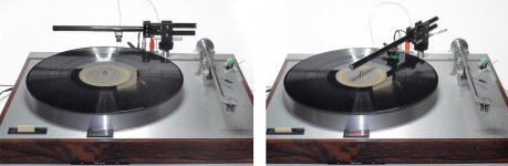
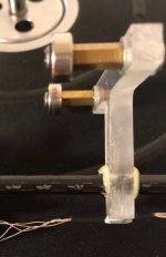
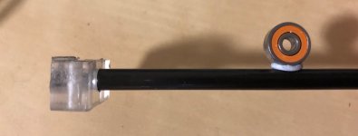
For the original design, does it make sense to add a bearing for vertical plane?
In the original design the play in the lateral bearing act as the vertical bearing. Adding a single bearing as you have shown would allow the armtube to rotate laterally due to the play in this bearing. It would also give you a double vertical pivot The advantage of placing a bearing in the position you have shown is that it puts the vertical pivot closer to the record. I think it's better to locate the lateral bearing closer to the record and allow the play to act as the vertical pivot.

Here's how I did it.
Niffy
Thanks Niffy, I am not sure if it is just my problem, with original design it’s very hard to set the vtf, a little bit touch can change it due to friction on vertical.
When I was using ballrace bearings I had the same problem. I found that by repeatedly raising and lowering the arm the reading on the scale settled down and became more consistent. I would initially set the manufacturers recommended force and fine tune by ear.
Niffy
Niffy
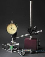
Hi Niffy - your scale rig is so smart that I couldn't resist.
Here is a simple version, some bits of plexy and a screw whose height can be measured with a digital caliper or a dial gauge.
Of course I measured the AT95 cartridge of my old test, with results that + or - confirm yours.
horizontal
0.5 gr = 0.14 mm -- 1 gr = 0.26 mm -- 1.5 gr = 0.35 mm*
vertical
0.5 gr = 0.11 mm -- 1 gr = 0.18 mm --1.5 gr = 0.28 mm -- 2 gr = 0.32 mm -- 2.5 gr = 0.44 mm*
given that on the vertical there is the VTF pre-loading I wanted to see if this altered the compliance:
between 0 and 1 gr = 0.18 mm --- between 1 gr and 2.5 (1.5VTF +1gr) = 0.26 mm.
Interesting, like the fact that unscrewing does not give the same values, as if the elastomer maintained the compression.
Conclusion: none. Maybe each cartridge tells a different story, and the matching of the arm ....
Making the first Lil Casey I learned at my expense that the effects of the effective masses may be much more evident than resonances: pure inertia that comes unpleasantly into play with the accelerations caused by warps and eccentricity.
Carlo
*(subtract to this data the deflection of the scale - about 10%)
Attachments
Hi Carlo,
Love the plexiglass box. For consistency between our measurements it looks like you have exactly the same scales I was using. I do believe that you are correct in saying that each cartridge tells a different story. I have diamond a closer look at your figures when I get a chance.
Niffy
Love the plexiglass box. For consistency between our measurements it looks like you have exactly the same scales I was using. I do believe that you are correct in saying that each cartridge tells a different story. I have diamond a closer look at your figures when I get a chance.
Niffy
Hi Carlo,
The deflections you measured do seem to be in keeping with the manufacturers specs. Your average lateral compliance is 21.4um/mN which is pretty close to the published 20um/mN. Vertically the compliance is 16.8um/mN. The difference in vertical and lateral static compliance is very similar to the difference I found with my cartridge. This would seem to suggest that vertical static compliance is normally lower than lateral. A larger sample group than just two examples would be required to confirm this. How does this relate to dynamic compliance?
Niffy
Sorry. typing error when transcribing my notes
vertical
0.5 gr = 0.11 mm -- 1gr = 0.18 mm --1.5 gr = 0.28 mm -- 2 gr = 0.37 mm -- 2.5 gr = 0.44 mm*
A marked difference when pre-loaded or not.
Fascinating test indeed - measures are always something to face, sparing lot of chats
carlo
Dynamic compliance even more complex: those different measures found while unscrewing are a symptom
Last edited:
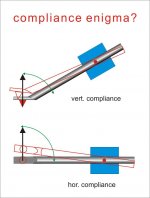
Being the elastomer a cylinder of homogeneous material, where comes from the difference between vert. and hor. compliance? (if there is one)
Can this be the (simple) solution?
Another step:
When making my kitchen test, pulling 1gr = 0.38 mm deflection, i was seeing the effects of 1gr side force + 2gr VTF, acting together. (real tracking+ friction conditions). Different from the scale test, that examines a single force
c2
what a complicate hobby
Attachments
Last edited:
Some cartridges* elastomers are not cylindrical. Some are shaped to have different compliance in both the axis. There was discussion about this in a thread which I forgot.
*(Not the one which is being tested)
Regards
*(Not the one which is being tested)
Regards
Probably, they have made so many...
But just considering the vectors: vert. compliance = compliance sin theta
Now what is the advantage they wanted to get with different compliances?
carlo
But just considering the vectors: vert. compliance = compliance sin theta
Now what is the advantage they wanted to get with different compliances?
carlo
Now since the stylus moves in 45° direction for pure L or R signal, shouldn't be the horizontal and vertical compliance the same? Or should we consider the stereo signal as vector sum of monophonic (L+R, horizontal stylus movement) and spatial signal responsible for the stereo effect (L-R, vertical stylus movement)? In the latter case the difference in hor and vert compliances could cause narrowing or widening the stereo field.
Or not, because the stylus follows the shape of the groove in either case. Perhaps the intention was to move the horizontal and vertical resonance frequencies apart from each other, maybe in accordance to the difference of the excitation signal in the two different planes.
Or not, because the stylus follows the shape of the groove in either case. Perhaps the intention was to move the horizontal and vertical resonance frequencies apart from each other, maybe in accordance to the difference of the excitation signal in the two different planes.
Last edited:
Hi Carlo
Having different compliances will work in a very similar way to having different effective masses. Most tonearm manufacturers seem to have similar vertical and lateral effective masses. By making the lateral compliance higher the resonant frequency laterally will be lower. If the tests we've performed are an accurate indication the difference in resonant frequency will not be great, about 10%. As eccentricity and lateral groove modulation start/occur at lower frequencies than warps and vertical modulation having the resonant frequency tuned to a lower frequency laterally makes sense. This is assuming that the difference in static compliances are continued in the dynamic compliances.
The difference in compliance could indeed be partially due to the fact that the cantilever is sloping as shown in your diagram. With a 20° tracking angle you could expect a difference of up to 10%. Our tests have shown a difference closer to 20% so it would seem that, as Hiten pointed out, the elastomer is purposely shaped to give different compliances.
Niffy
- Home
- Source & Line
- Analogue Source
- DIY linear tonearm