Super10018 - Wich pivot? as in many commercial linear trackers there will be a snap lock (see exploded view # 2630, ) to prevent any involuntary rotation. For convenience the rotation is counterclockwise
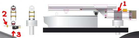
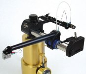
Please see attached photo. The pivot I was talking about marked 1. I understand the mechanism on the pivot is to deal with wrap. Let's look the needle position, marked 3. The stylus is directly under the rail. Why do you need to do this? Any benefits to position the stylus directly under the rail? If the stylus is placed directly under the rail, wrap will cause problem for sure. So, a mechanism to deal with wrap is necessary. But how about move the stylus away from the rail just as everyone else does? The distance from the tips of stylus to center of air bearing shaft are between 3"-2.5" for my air bearing arms. I also have an outer ring to prevent wrap problem. I have never encounter problems caused by wrap. The same distance for Niffy's design is even shorter than mine. I never see he says there is a problem with wrap. In addition, he doesn't even have an outer ring. You have a counter weight in front so the total mass of carriage may be same as or heavier than it is on the back as most of people do. The total mass of carriage is very critical for a mechanical linear arm. Placing the stylus directly under the rail doesn't help you to reduce the total mass of carriage. So, why need to do it?
Once you reposition the stylus away from the center of rail, you don't need anything to deal with wrap problem. Horizontal and vertical masses may not be exactly same. The difference is very small, 1 Hz or less, on my air bearing arms. I believe it may even smaller for Niffy's design since his head shell is shorter than mine.
Attachments
Last edited:
Btw, I am not fond of the construction of ball rail. The piece of metal to hold balls in place may increase the total mass of carriage significantly.
I understand the mechanism on the pivot is to deal with wrap.
Jim, your concerns are well reasoned. But I think you misunderstood Carlo's intent. I cannot fully speak for Carlo but I can provide my own observation. The parallelogram is NOT for dealing with warp. It is the VERTICAL bearing. He wants to separate vertical movement from the horizontal carriage. He wants to make horizontal bearing and vertical bearing independent from each other -- inspired by our esteem member Ralf's brilliant design. The parallelogram is his version of a pistonic bearing for purely vertical movement so the main "arm" doesn't need pivot/seesaw movement. That's why the stylus is underneath the center of the sliding carriage. Since the carriage design is a self centering kind that he needs equal mass on both side of the stylus, front and back. The reason he and I mentioned warps is that my concern about parallelogram can create subtle horizontal shift when going up and down, much like dealing with a warp records. Unless it's severe warp record, horizontal distance should not be a concern. Due to the "Roberval balance" the horizontal placement of the carriage does not affect VTF, a good thing! I think it will work adequately as an alternative parallel tracker.
Btw, I am not fond of the construction of ball rail. The piece of metal to hold balls in place may increase the total mass of carriage significantly.
I have to admit that I am with you when it comes to his carriage design. There's just too much horizontal mass that it negates the benefit of having a purely horizontal sliding carriage, a mini wagon like carriage is more to my own liking. And the self centering system doesn't seem very stable under dynamic behavior. We spend all the effort to shorten the arm and eliminate the lever, pivot, etc... and then you have this hulking wide carriage doesn't seem very elegant to me.
DD,
Well, if this is the propose of parallelogram, things become even simpler. Almost all the regular linear tracking arms have separated vertical and horizontal bearings. Take Niffy's design as example, same wheels act as both vertical and horizontal bearings. Both movements are separated.
Jim
Well, if this is the propose of parallelogram, things become even simpler. Almost all the regular linear tracking arms have separated vertical and horizontal bearings. Take Niffy's design as example, same wheels act as both vertical and horizontal bearings. Both movements are separated.
Jim
Take Niffy's design as example, same wheels act as both vertical and horizontal bearings. Both movements are separated.
The point of his design is that he does NOT want a seesaw style vertical pivot. If purely vertical, there will be no VTA change at all, hence the parallelogram. You just have to let him experiment and check the result. He's having fun and let him have his buzz first. 🙂
Radial rail
Ouch, I stepped on a beehive!
Please understand my point of view: in 10 years I have experienced TA of all types, looking for limits (enjoying experiments, not trying to make the best arm in the world at home), but I have never done a linear for this simple reason:
(attachment - the chart is not mine)
As says a friend of mine, remaining with no gas you do not attack a 10-meter pole to push the car by the other side of the street
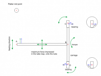
That video (#1957 Dd thread) made me think that was enough to overturn a normal linear (the arm oscillating on the rail becomes the rail oscillating on the arm) to be able to position the carriage (and the stylus) aligned with the side force (radially = no torque on carriage). # 2383
This is the only reason, a good reason imho. Maybe better than shortening the arm up to problematic measures (azimuth).
Ralf's arm - really brilliant - has nothing to do with this, here there is no separation (electrical and temporal) of movements, as in any passive mechanical arm: they are only applied in different points than in traditional TA<.
And now building details:
Carriage: non-recirculating linear bearing are used for no play and minimum friction movements in precision instruments, and someone used even on a linear TA
My Linear Tracker (a new variation perhaps?) An entire thread about
My experience comes from two versions of Syrinx PLT and Jr. Casey TA, slowly realizing that less balls means less friction (and probably less chattering). This cart will weight around 7 grams: if you have better ideas, better for me too. In normal linear carriages - even the most sophisticated ones - there is the arm + CW weight, and here not: so we start already with a nice advantage. The same for the self-centering movement: again consider that the rail too must weight almost nothing.
Vertical movement: nothing special, any scale, even with suspended plates, behaves like this. Now I have understood that here half parallelogram is enough, eliminating 4 bearings. Another step.
As I wrote in a post, at the beginning I tried too to make a piston cart (the most trivial solution, but too much precision, too much weight needed) and I have not succeeded. I design things that can be realized with my own means, not impracticable technologies.
Warps: half century ago I learned not to buy lopsided discs, and to keep my LPs properly. Warps must remain within the limits of decency. Imho the arms must be able to handle warps and eccentricity, not be designed for that. In Italy there was a (in)famous pre-phono designed especially not to hear the clicks of the dust, we're still laughing.
Thanks to all for your attention
carlo
Ouch, I stepped on a beehive!
Please understand my point of view: in 10 years I have experienced TA of all types, looking for limits (enjoying experiments, not trying to make the best arm in the world at home), but I have never done a linear for this simple reason:
(attachment - the chart is not mine)
As says a friend of mine, remaining with no gas you do not attack a 10-meter pole to push the car by the other side of the street
That video (#1957 Dd thread) made me think that was enough to overturn a normal linear (the arm oscillating on the rail becomes the rail oscillating on the arm) to be able to position the carriage (and the stylus) aligned with the side force (radially = no torque on carriage). # 2383
This is the only reason, a good reason imho. Maybe better than shortening the arm up to problematic measures (azimuth).
Ralf's arm - really brilliant - has nothing to do with this, here there is no separation (electrical and temporal) of movements, as in any passive mechanical arm: they are only applied in different points than in traditional TA<.
And now building details:
Carriage: non-recirculating linear bearing are used for no play and minimum friction movements in precision instruments, and someone used even on a linear TA
My Linear Tracker (a new variation perhaps?) An entire thread about
My experience comes from two versions of Syrinx PLT and Jr. Casey TA, slowly realizing that less balls means less friction (and probably less chattering). This cart will weight around 7 grams: if you have better ideas, better for me too. In normal linear carriages - even the most sophisticated ones - there is the arm + CW weight, and here not: so we start already with a nice advantage. The same for the self-centering movement: again consider that the rail too must weight almost nothing.
Vertical movement: nothing special, any scale, even with suspended plates, behaves like this. Now I have understood that here half parallelogram is enough, eliminating 4 bearings. Another step.
As I wrote in a post, at the beginning I tried too to make a piston cart (the most trivial solution, but too much precision, too much weight needed) and I have not succeeded. I design things that can be realized with my own means, not impracticable technologies.
Warps: half century ago I learned not to buy lopsided discs, and to keep my LPs properly. Warps must remain within the limits of decency. Imho the arms must be able to handle warps and eccentricity, not be designed for that. In Italy there was a (in)famous pre-phono designed especially not to hear the clicks of the dust, we're still laughing.
Thanks to all for your attention
carlo
Attachments
Last edited:
Carlo, I can see your point now. The challenge is attractive.
As to my understanding concerning linear arms, I'm still unable to grasp how to resolve a wiring problem, that is common with all LT known by me, with only one exclusion -it is solved by the Russian design (see video from my post 2362), by attaching additional pivoted tube (arm or lever).
My own experience with many traditional pivot arms showed that flexibility and shape of tonearm wires layout is often more important, than bearing friction, and is very influential as to both: sound and tracking ability. With pivot arms it is mainly solved due to leverage momentum and proper shape of the wire loop.
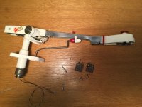
With LTA it seems, like nobody cares too much. I'm still unable to grasp, what is the advantage in having no skating force with LT, if we still have those loops of wires, hanging around, affecting tracking and sound. They are also unshielded, prone to cause hum.(see attached pics). By those pictures, I may expect lateral forces , far exceeding those caused by skating force in pivot arms.
Can someone, who is experienced with LTA, enlighten me, as to wire loop?
As to my understanding concerning linear arms, I'm still unable to grasp how to resolve a wiring problem, that is common with all LT known by me, with only one exclusion -it is solved by the Russian design (see video from my post 2362), by attaching additional pivoted tube (arm or lever).
My own experience with many traditional pivot arms showed that flexibility and shape of tonearm wires layout is often more important, than bearing friction, and is very influential as to both: sound and tracking ability. With pivot arms it is mainly solved due to leverage momentum and proper shape of the wire loop.
With LTA it seems, like nobody cares too much. I'm still unable to grasp, what is the advantage in having no skating force with LT, if we still have those loops of wires, hanging around, affecting tracking and sound. They are also unshielded, prone to cause hum.(see attached pics). By those pictures, I may expect lateral forces , far exceeding those caused by skating force in pivot arms.
Can someone, who is experienced with LTA, enlighten me, as to wire loop?
Attachments

Last edited:
Hi all,
Well Carlo, as ever you take the box step out of it then kick said box to pieces. This truly is an innovate piece of design. I do have a couple of concerns about the overall design one of which I can see a simple solution to and one that I can't.
First I would like to address an assertion made by directdriver.
Having the cartridge moving purely vertically will not eliminate VTA error. When dealing with warps with a seesaw style vertical pivot only a small proportion of VTA error is due to rotation about the vertical pivot. The majority of this error is due to the slope of the surface of the record. Warps are often referred to as hill and dale. Between the bottom of a dale to the top of a hill the ground slopes upwards. Having the cartridge moving purely vertically WILL eliminate VTA error due to a pivot but will have NO effect on VTA error due to the slope of the record surface. It is true, with vertically pivoted arms, that shorter arms will have greater pivot angles than longer arms and therefore have greater overall VTA error. A purely vertically moving cartridge would be the same as an infinitely long arm in this respect. When designing my record clamping system I measured the actual warps of a random sample of my record collection. Using this information I modelled the effect of different arm lengths on VTA error. I found that you would need to reduce arm length to about 30mm before VTA error due to pivot rotation became as significant as that due to the slope of record surface.
I personally use a reflex clamping system that has a small hump under the centre of the record and a screw down clamp that only contacts near the edge of the label. This eliminates all but the most severe warps. The addition of a ring clamp or vacuum hold down would be the only way to improve this but would make little or no difference on the majority of records.
One definite advantage of a purely vertical movement is that variation in the thickness of records would have NO effect on VTA error whereas with any pivoted arm it will have an effect however small.
My first concern regarding Carlo's arm is the lack of constraint on the rotation of the carriage to prevent it from swinging. I understand that by placing the stylus directly underneath the rail vertical movement of the record will translate directly into vertical movement of the rail with no twisting moments being introduced. Also the addition of the weight in front of the cartridge will keep the carriage balanced. This would be great if the only force acting on the stylus was purely vertical. However a significant force acting on the stylus is that due to stylus drag. This will pull the cartridge forwards causing the carriage to rotate on the lateral bearing. This can be remedied by making the lateral bearing into a dual rail design. This would eliminate the need for the balancing weight in front of the cartridge. It would require an additional mechanism to allow for VTA adjustment. The downside would be that it would increase the mass of the system.
This brings me onto my main concern. The vertical effective mass of this arm is going to be enormous. As the cartridge, carriage and rail all move vertically together their actual mass will be the vertical effective mass, similar to how the total moving mass of a linear tracker is its horizontal effective mass. Additionally the counterweight also contributes to the effective mass. Your mock up shows the length of the levers being about the same on the rail and counterweight sides of the vertical pivot. In this configuration the counterweight would have to be about the same mass as the cartridge, carriage, rail system and would therefore double the vertical effective mass. The horizontal effective mass would be only the mass of the cartridge and carriage combined. The vertical effective mass would be significantly greater than the horizontal. The horizontal effective mass should be equal to or greater than the vertical effective mass. Ideally, based on my calculations, the horizontal effective mass should be about 4-5 times greater than the vertical effective mass. Vertical and horizontal effective masses are dealing with different aspects of replay and DO NOT need to be the same dispite what mainstream "wisdom" claims. Unfortunately I cannot see a simple solution to this gross discrepancy.
The design does have a couple of points definitely going in its favour. As the carriage is going to be very small it will naturally have a high resonate frequency. This will reduce colouration due to bending modes within the carriage. In a conventional arm bending modes are the greatest source of colouration, much greater than cartridge alignment for instance. Also by making the carriage small compression waves (sound waves) and their reflections are much less problematic.
Keep kicking that box to pieces.
Niffy
Well Carlo, as ever you take the box step out of it then kick said box to pieces. This truly is an innovate piece of design. I do have a couple of concerns about the overall design one of which I can see a simple solution to and one that I can't.
First I would like to address an assertion made by directdriver.
The point of his design is that he does NOT want a seesaw style vertical pivot. If purely vertical, there will be no VTA change at all, hence the parallelogram. You just have to let him experiment and check the result. He's having fun and let him have his buzz first. 🙂
Having the cartridge moving purely vertically will not eliminate VTA error. When dealing with warps with a seesaw style vertical pivot only a small proportion of VTA error is due to rotation about the vertical pivot. The majority of this error is due to the slope of the surface of the record. Warps are often referred to as hill and dale. Between the bottom of a dale to the top of a hill the ground slopes upwards. Having the cartridge moving purely vertically WILL eliminate VTA error due to a pivot but will have NO effect on VTA error due to the slope of the record surface. It is true, with vertically pivoted arms, that shorter arms will have greater pivot angles than longer arms and therefore have greater overall VTA error. A purely vertically moving cartridge would be the same as an infinitely long arm in this respect. When designing my record clamping system I measured the actual warps of a random sample of my record collection. Using this information I modelled the effect of different arm lengths on VTA error. I found that you would need to reduce arm length to about 30mm before VTA error due to pivot rotation became as significant as that due to the slope of record surface.
I personally use a reflex clamping system that has a small hump under the centre of the record and a screw down clamp that only contacts near the edge of the label. This eliminates all but the most severe warps. The addition of a ring clamp or vacuum hold down would be the only way to improve this but would make little or no difference on the majority of records.
One definite advantage of a purely vertical movement is that variation in the thickness of records would have NO effect on VTA error whereas with any pivoted arm it will have an effect however small.
My first concern regarding Carlo's arm is the lack of constraint on the rotation of the carriage to prevent it from swinging. I understand that by placing the stylus directly underneath the rail vertical movement of the record will translate directly into vertical movement of the rail with no twisting moments being introduced. Also the addition of the weight in front of the cartridge will keep the carriage balanced. This would be great if the only force acting on the stylus was purely vertical. However a significant force acting on the stylus is that due to stylus drag. This will pull the cartridge forwards causing the carriage to rotate on the lateral bearing. This can be remedied by making the lateral bearing into a dual rail design. This would eliminate the need for the balancing weight in front of the cartridge. It would require an additional mechanism to allow for VTA adjustment. The downside would be that it would increase the mass of the system.
This brings me onto my main concern. The vertical effective mass of this arm is going to be enormous. As the cartridge, carriage and rail all move vertically together their actual mass will be the vertical effective mass, similar to how the total moving mass of a linear tracker is its horizontal effective mass. Additionally the counterweight also contributes to the effective mass. Your mock up shows the length of the levers being about the same on the rail and counterweight sides of the vertical pivot. In this configuration the counterweight would have to be about the same mass as the cartridge, carriage, rail system and would therefore double the vertical effective mass. The horizontal effective mass would be only the mass of the cartridge and carriage combined. The vertical effective mass would be significantly greater than the horizontal. The horizontal effective mass should be equal to or greater than the vertical effective mass. Ideally, based on my calculations, the horizontal effective mass should be about 4-5 times greater than the vertical effective mass. Vertical and horizontal effective masses are dealing with different aspects of replay and DO NOT need to be the same dispite what mainstream "wisdom" claims. Unfortunately I cannot see a simple solution to this gross discrepancy.
The design does have a couple of points definitely going in its favour. As the carriage is going to be very small it will naturally have a high resonate frequency. This will reduce colouration due to bending modes within the carriage. In a conventional arm bending modes are the greatest source of colouration, much greater than cartridge alignment for instance. Also by making the carriage small compression waves (sound waves) and their reflections are much less problematic.
Keep kicking that box to pieces.
Niffy
Hi Niffy, I was waiting impatiently for your contribution, as always at the heart of the problems. If you have 2 concerns mine are very similar to yours, but more numerous. I will answer carefully as soon.
Meanwhile, the VTA: great! is always surprising to check wrong beliefs stored from years: you're absolutely right
ciao carlo
Meanwhile, the VTA: great! is always surprising to check wrong beliefs stored from years: you're absolutely right
ciao carlo
Attachments

One definite advantage of a purely vertical movement is that variation in the thickness of records would have NO effect on VTA error whereas with any pivoted arm it will have an effect however small.
Just that alone is probably worth the effort. I know some audiophiles would not buy a tonearm without on-the-fly VTA adjustment, which makes me wonder if these people actually have time to listen to music. It has been my own obsession to think of ways to eliminate this tedious need to adjust VTA constantly. Once again thank you for your lucid explanation and open-mindedness.
Carlo, logical: long arm good, short arm bad. Infinite length arm best (as per your 3rd picture) 😉Hi Niffy, I was waiting impatiently for your contribution, as always at the heart of the problems. If you have 2 concerns mine are very similar to yours, but more numerous. I will answer carefully as soon.
Meanwhile, the VTA: great! is always surprising to check wrong beliefs stored from years: you're absolutely right
ciao carlo
Carlo, I can see your point now. The challenge is attractive.
As to my understanding concerning linear arms, I'm still unable to grasp how to resolve a wiring problem, that is common with all LT known by me, with only one exclusion -it is solved by the Russian design (see video from my post 2362), by attaching additional pivoted tube (arm or lever).
My own experience with many traditional pivot arms showed that flexibility and shape of tonearm wires layout is often more important, than bearing friction, and is very influential as to both: sound and tracking ability. With pivot arms it is mainly solved due to leverage momentum and proper shape of the wire loop.
With LTA it seems, like nobody cares too much. I'm still unable to grasp, what is the advantage in having no skating force with LT, if we still have those loops of wires, hanging around, affecting tracking and sound. They are also unshielded, prone to cause hum.(see attached pics). By those pictures, I may expect lateral forces , far exceeding those caused by skating force in pivot arms.
Can someone, who is experienced with LTA, enlighten me, as to wire loop?
Wire is not a problem at all. I use 4 strands of 44 g wires from a broken HD600 headphone wire for each channel. Bearing friction is the most important factor for linear arms. Wires don't need to be shielded. I have no problem with electronic interference at all. In fact, my arms are very quiet. Some of your photos are air bearing arms. For air bearing arms, air tubing may cause more problem than wire. However, on my own air bearing arm, I use 1/32" tubing which can hold up to 90 psi. I think it is better than any air tubings used on commercial versions of air bearing arms.
these look good especially if the size and weight could be reduced 5 - 10x.
possibly a magnetic bearing on a 1/8 inch shaft to hold cartridge and tracking counterbalance.
possibly a magnetic bearing on a 1/8 inch shaft to hold cartridge and tracking counterbalance.
I have to agree with Super as the wire is not the problem with hum, ground loops are and need attention.
I have a spool of litz and have used the Cardas tonearm wire on many LT situations and never had hum issues that came from it specifically so need to stress over its arrangement
Regards
David
I have a spool of litz and have used the Cardas tonearm wire on many LT situations and never had hum issues that came from it specifically so need to stress over its arrangement
Regards
David
Hi walterwalter,
I tried quite a few different arm cable set ups before I settled on my current configuration. I use 4 x 0.06mm enamel magnet wire per channel reasonable tightly twisted, two for positive and two for negative. The separate bundles for left and right channels run independently and are not twisted together.
When designing the bearings for my arm I built a test rig to measure lateral friction. The test rig had a resolution of about 0.2mN (0.02g). I did a quick test with my current arm cable to see how much drag it added. I couldn't detect any increase in drag. (The measurements were not as thorough as those used to test the bearings, only about 30 separate measurements were taken with the cable added as opposed to 250-300 when measuring just the bearings). From this I can conclude that the amount of additional drag due to the arm cable is lower than the resolution of the test rig ie less than 0.02g.
Drag due to the arm cable really is a non-issue.
Niffy
Carlo, logical: long arm good, short arm bad. Infinite length arm best (as per your 3rd picture)
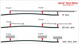
Walter, after Niffy's post I can no longer agree. What you say, what I thought, is what tells the common sense referring to the horizontal plane of a perfectly flat disc **. But if you refer correctly to the tangent to the groove, a quick graphic check indicates
bad warp (very steep - 5mm high)
9 " arm + - 3.5 ° deflection --- 50 mm arm + - 3.0 ° deflection --- infinite arm + - 4.0 ° deflection
"good" warp (less steep, same 5mm high)
9 " arm + - 3.0 ° deflection --- 50 mm arm + - 3.0 ° deflection --- infinite arm + - 3.0 ° deflection
Surprising - the vert movement (infinite arm) may be worse than the other two
carlo
** where there will never be a vertical displacement
Attachments
HI Niffy, again.
Having the cartridge moving purely vertically will not eliminate VTA error...
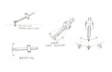
The goal of this arm is mainly to have a radial cart; I consider the error of azimuth on the tangent a bad thing I'm used to, it worries me a lot more that on the radius, not often mentioned because the commercial arms almost always have fixed headshells. Among other things, I observed that even the stylus bending can generate it (sketch).
This arm may work perhaps with both the pivoted solution (as in the test) and the parallelogram. Both have pros and cons. The question now is if it works and then, eventually, of how;
My first concern regarding Carlo's arm is the lack of constraint on the rotation of the carriage to prevent it from swinging .... This can be remedied by making the lateral bearing into a dual rail design.
The carriage swing, due stylus drag, is a major problem, purposely explored in test with a carriage prone to rotate, with the referred results. The designed solution has 2 rails (very close, unfortunately, to have an acceptable weight) and a round section for self centering. In my previous tests if this taper increases (diagonal square section) also increases the stiction, due the pressure of the spheres on the walls. Really a difficult compromise
The vertical effective mass of this arm is going to be enormous
Yes, a hard battle, difficult to go under 45 gr (rail + cart + cartridge). But in the test with a weight > 70 gr nothing terrific emerged. Those arms length brought to a CW of 230 gr, and consequent frictions: I had to use ball bearings to make it rotate properly. With the parallelogram the CW would drop to 50-60. The eff mass instead changes only a little, imho.
The horizontal effective mass would be only the mass of the cartridge and carriage combined
Exactly so, not having the weight of an arm and CW, should be better than in normal Lt, where is a mayor concern both for masses and stiction (you did an incredible work on it)
As the carriage is going to be very small...
As for the resonances i'm not so optimistic, such a small "indipendent" mass worries me a lot (i believe in "mechanical grounding"): it will depend on how stable the contact between spheres and rail will be: another reason to use only 4 spheres
carlo
Having the cartridge moving purely vertically will not eliminate VTA error...
The goal of this arm is mainly to have a radial cart; I consider the error of azimuth on the tangent a bad thing I'm used to, it worries me a lot more that on the radius, not often mentioned because the commercial arms almost always have fixed headshells. Among other things, I observed that even the stylus bending can generate it (sketch).
This arm may work perhaps with both the pivoted solution (as in the test) and the parallelogram. Both have pros and cons. The question now is if it works and then, eventually, of how;
My first concern regarding Carlo's arm is the lack of constraint on the rotation of the carriage to prevent it from swinging .... This can be remedied by making the lateral bearing into a dual rail design.
The carriage swing, due stylus drag, is a major problem, purposely explored in test with a carriage prone to rotate, with the referred results. The designed solution has 2 rails (very close, unfortunately, to have an acceptable weight) and a round section for self centering. In my previous tests if this taper increases (diagonal square section) also increases the stiction, due the pressure of the spheres on the walls. Really a difficult compromise
The vertical effective mass of this arm is going to be enormous
Yes, a hard battle, difficult to go under 45 gr (rail + cart + cartridge). But in the test with a weight > 70 gr nothing terrific emerged. Those arms length brought to a CW of 230 gr, and consequent frictions: I had to use ball bearings to make it rotate properly. With the parallelogram the CW would drop to 50-60. The eff mass instead changes only a little, imho.
The horizontal effective mass would be only the mass of the cartridge and carriage combined
Exactly so, not having the weight of an arm and CW, should be better than in normal Lt, where is a mayor concern both for masses and stiction (you did an incredible work on it)
As the carriage is going to be very small...
As for the resonances i'm not so optimistic, such a small "indipendent" mass worries me a lot (i believe in "mechanical grounding"): it will depend on how stable the contact between spheres and rail will be: another reason to use only 4 spheres
carlo
Attachments
Thank you all. Now I can see, that my concern about wiring is a bit exaggerated.
Super 10018, I've also found the headphone wires are among the most flexible for wiring the arms.
Avwerk, In my setup, I'm still having some hum issues with some LOMC cartridges, if the arm wires are unshielded.
Niffy, If your tests prove that the bearing friction is crucial, I would believe it and concentrate on bearings.
Nocdplz, with your current parallelogram design, you can cut in half it's vertical mass, if substitute the counterweight with spring compensator (as with many ancient arms). It was a very effective solution, as with idler drives, causing a lot of vibrations and rumble, and spring counterweight arms are almost immune (20dB down) to rumble as well, as to acoustical feedback. They resonate very differently from average arms, because the center of mass is near the cartridge, not near the bearing, as with ''normal'' arm.
Attachments
Last edited:
3 dimensional warps and azimuth
Hi all,
When considering warps we tend to look at them in a 2 dimensional manner, only really looking parallel to the groove, and how this effect VTA. In reality warps are 3 dimensional, they not ony slope up and down parallel to the groove but also slope perpendicular to the groove. Warps not only effect VTA but also effect azimuth.
When I measured my random selection of records I only measured parallel to the groove so regrettably didn't get any data as to the slope of the record surface perpendicular to the groove. I think that the average slope of the record surface is probably going to be similar for VTA and azimuth but the maximum amount of slope for azimuth is probably higher than the maximum slope for VTA. As I said I haven't actually measured this so I may be wrong. With VTA the average slope up is equal to the average slope down. However with azimuth the average slope tends to be towards the centre of the record. For this reason perfect azimuth alignment will tend to require the cartridge to be ever so slightly twisted counterclockwise. What is certain is that warps effect azimuth.
The alignment of the stylus with the groove consists of 3 parameters, LTA, VTA, and azimuth. Try and picture an idealized fine line stylus sitting in a groove. Now imagine misaligning the stylus in by a small amount for LTA. Do the same thing for VTA and azimuth. (I would have made a couple of diagrams to visually assist but I'm currently recovering from an operation and sitting at my computer is not comfortable) From this mental image you can probably see that azimuth misalignment will have the greatest effect and LTA the least effect. This holds up in my personal experience with the sonic effects of altering each of the alignment parameters.
As azimuth alignment is the most important it may seem odd to design an arm that doesn't have azimuth adjustment. There are 2 main reasons why this adjustment is often not included. The first is that a solidly attached headshell/armtube is more rigid and offers a more direct conduit for compression waves. The second is that making an adjuster that allows accurate fine movement to a fraction of a degree is difficult. Most adjusters simply rely on loosening the headshell/armtube and rotating by hand. Trying to do this to an accuracy of less than a couple of degrees is virtually impossible, just not good enough.
My method was to build the carriage as accurately as possible with no adjustment and zero azimuth, then clamp the record to minimize warps. Of course this cannot account for the accuracy of manufacture of my cartridge but it seems to work pretty well.
Now for an off topic observation that highlights another area where the common wisdom used by many manufacturers (and diyers) is often flawed.
Many manufacturers align their vertical bearing so that it is perpendicular to the groove/cantilever. A couple of examples are SME and Rega. These are the arms where the bearing yoke is not at 90° to the armtube but is twisted to match the offset angle. The idea is that as the cartridge moves up and down as it navigates a warp the cartridge remains parallel to the surface of the platter (laterally) and the azimuth angle won't change.
If the bearing yoke is at 90° to the armtube the cartridge will rotate ever so slightly counterclockwise as the arm raises resulting in an azimuth error. Seems reasonable.
However as warps are not 2 dimensional but are 3 dimensional this wisdom falls apart. As I mentioned earlier warps tend to slope more towards the centre of the record requiring the cartridge to be twisted slightly counterclockwise to compensate. Due to this the arm with the bearings at 90° to the armtube will actually have LOWER azimuth error than the arm with the bearings matching the offset angle. In fact twisting the bearings even further in the opposite direction to the offset angle will further reduce azimuth variation due to warps. The ideal angle will be dependent upon the actual average slope of the warps and has to account for variation in the thickness of records. My rough calculations (based on guesstimates of the angle) would suggest an angle of 15-20°. If I discount variation in record thickness this angle could be as much as 45°. Of course with a perfectly flat record this angle would make no difference. Unfortunately as the perceived wisdom is so ingrained in the hi-fi press any manufacturers aligning their bearings in such a manner would get a rough ride. End of off topic.
Niffy
Hi walterwalter,
I had often wondered if it was possible to build a linear arm with a spring counterbalance. It looks like you might have found a way to do just that. Good observation. I agree that for this arm a spring counterbalance could have definite advantages not least being the reduction of vertical effective mass (maybe to as much as half).
Niffy
- Home
- Source & Line
- Analogue Source
- DIY linear tonearm