Thanks Walter - interesting idea the springy counterweight. I've used one (only in an auxiliary role) on the Rabbit PLT to decrease the torque of the CW on cranks, and gave no problems. But I have no idea how to calculate the eff. mass for a spring: you are saying it reduces in half - why?
carlo
carlo
Carlo, if you use spring instead of the counterweight, you just minus the complete mass of the counterweight. Spring doesn't have the mass (it is miniscule), no inertia, the force it introduces, isn't based on mass or gravitation.. And so, it doesn't add any mass to the rest of the arm. More precise, it's mass together with tension regulator is almost negligible. I would say that your parallelogram design crying for it...
I haven't thoroughly investigated spring counterbalances so I'm kind of thinking out loud here.
When calculating the vertical resonant frequency for an arm using a counterweight the two main factors are effective mass of the arm and compliance of the cartridge. (let's ignore damping as it complicates things)
With a spring counterbalance you still have the effective mass of the arm and the compliance of the cartridge. You also have a second compliance which is the spring used for the counterbalance. The effective mass as seen buy the counterbalance spring will almost always be different to that seen by the cartridge as they are normally at different distances from the pivot.
The compliance of the cartridge and the compliance of the counterbalance will act in parallel to give a combined compliance. To do this you would need to calculate an equivalent compliance for the counterbalance spring as if it were located at the stylus. A bit of a complicated idea. As it is a single system it will not try and resonate at two different frequencies at once it will resonate at a single system dependent frequency.
In Carlo's design the length of the levers appears to be the same on the rail side as the counterweight sides which simplifies matters greatly. In this case the effective mass will be the combined mass of the cartridge, carriage, rail and spring attachment plus about half the mass of the levers. The combined compliance in the case would be just the reciprocals of the sum of the reciprocals of the two compliances. More simply the sum of the stifnesses. By choosing a counterbalance spring of a suitable compliance it should be possible to tune the overall system resonance to the desired 10hz or so.
This may be a way of overcoming the high vertical effective mass problem. If you can't reduce the mass maybe you can reduce the compliance.
Hopefully this makes sense to someone other than me or that someone can point out if I've made a mistake.
Niffy
Last edited:
The issue with a spring is that the force is not constant, it is rather a function of displacement. If we consider a warped disc, the VTA will be modulated.
The issue with a spring is that the force is not constant, it is rather a function of displacement. If we consider a warped disc, the VTA will be modulated.
True. But.
If the spring is attached close to the pivot the extension/compression required to allow for even a severe warp will be very small. Even if the spring has to extend by the same degree as the height of the warp the amount of extension would still be small, normally only a fraction of a millimetre. If the counterweight spring is also made as long as possible the load on the spring will be almost perfectly linear across the range of motion. For complete overkill you could use a variable rate spring but I really don't think that this is necessary.
With a conventional counterweight tonearm, if its centre of mass is not exactly level with the pivot the restorative force will not be linear either.
I can see no reason why a spring counterbalance can't be as linear as a gravity counterweight.
(Did you mean VTF when you said VTA would be modulated as I don't see how VTA would be modulated)
Niffy
#2419 -- In reality warps are 3 dimensional, they not ony slope up and down parallel to the groove but also slope perpendicular to the groove. Warps not only effect VTA but also effect azimuth.
Hey Niffy, where have scavenged your records, atomic Bikini atoll? crematorium oven for extinct loved LPs? Never seen hor. warps, bad vert ones just before throwing all away .. 😉
Trying to do this to an accuracy of less than a couple of degrees is virtually impossible, just not good enough.
If the headshell allows azimuth adjustment (every gentleman should have one), to do this use a T shaped plexy gadget, perfectly squared, support it on the platter, press the headshell on. and tighten the screw.
Then fix your cartridge and start crying, because the precision allowed by the elastomer (more if aged) is unfortunately very far from the precision you're talking about.
Quote all, especially the off topic: a remedy worse than the damage.
ciao - Carlo
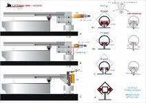
Niffy, it is true. If the spring is short, and act closer to vertical, VTF will vary a lot (pic. 1). If the spring is long, positioned horizontally, and closer to horizontal bearing, VTF will be very close to constant, even with bad warps. That's why Garrard engineers extended spring up to the front, over the bearing(pic. 2)True. But.
If the spring is attached close to the pivot the extension/compression required to allow for even a severe warp will be very small. Even if the spring has to extend by the same degree as the height of the warp the amount of extension would still be small, normally only a fraction of a millimetre. If the counterweight spring is also made as long as possible the load on the spring will be almost perfectly linear across the range of motion. For complete overkill you could use a variable rate spring but I really don't think that this is necessary.
With a conventional counterweight tonearm, if its centre of mass is not exactly level with the pivot the restorative force will not be linear either.
I can see no reason why a spring counterbalance can't be as linear as a gravity counterweight.
Actually, I'm thinking about the linear arm design with spring counterbalance for a long time, and I see some interesting solutions. The main obstacle (in my case) is precise and expensive machining.
Attachments
radial rail TA
Some rough calcs for the vertical mass, with the usual spreadsheet for pivoted arms.
First pivoted version: I set the rail as the headshell - cartridge+cart as screws and cartridge, the rest as in a normal pivoted TA.
eff length15 cm: CW 160 gr at 4 cm - (rail + cart + cartridge) 42 g - arms 15 g >> eff mass = 29.1
eff length 11 cm: CW 120 g at 4 cm - (rail + cart + cartridge) 42 g - arms 12 g >> eff mass = 26.2
New parallelogram version: I considered like a mini pivoted, with all the weights (rail + cart + cartridge = 42g) loaded on the end of the parallelogram's small arm.
eff length 4 cm: CW 50 g at 3 cm - (rail + cart + cartridge) 42 g - arms 3 g >> eff mass = 28.3
the Hor. mass is equal to the weight force (cart + cartridge) 17 g >> eff mass = 17
As expected the vert eff. mass does not change much between the two versions. (CW weight very much, instead). It's high, but not impossible (near some well known TA). The horizontal mass is moderate, not too different from the Vert. one and could be paired easily. For me, knowing so little, is good, but there are different opinions around.
carlo
Spring CW parallelogram version - Setting the spring as CW 2 gr, the minimum allowed
eff length 4 cm: CW 2 gr at 3 cm - (rail + cart + cartridge) 42 g -- arms 3 g >> eff mass = 4.1 (???)
Walter and Niffy -- seems too good to be true: really the spring has no influence on the inertia in any way? seems not so simple
Effective mass (spring–mass system - Wikipedia)
To be further investigated...
Last edited:
#2419 -- In reality warps are 3 dimensional, they not ony slope up and down parallel to the groove but also slope perpendicular to the groove. Warps not only effect VTA but also effect azimuth.
Hey Niffy, where have scavenged your records, atomic Bikini atoll? crematorium oven for extinct loved LPs? Never seen hor. warps, bad vert ones just before throwing all away .. 😉
Trying to do this to an accuracy of less than a couple of degrees is virtually impossible, just not good enough.
If the headshell allows azimuth adjustment (every gentleman should have one), to do this use a T shaped plexy gadget, perfectly squared, support it on the platter, press the headshell on. and tighten the screw.
Then fix your cartridge and start crying, because the precision allowed by the elastomer (more if aged) is unfortunately very far from the precision you're talking about.
Quote all, especially the off topic: a remedy worse than the damage.
ciao - Carlo
I don't think I understand your reply.
The records I measured were randomly selected for my record collection. Some are records I play regularly and some rarely played. I built a test rig specifically for measuring warps. The measurements were taken at the lead in groove where warps will tend to be at their worst. The measurements taken were accurate to a resolution of 10um (0.01mm) of vertical displacement. Records were measured both with and without the use of a clamp. Several of the records were measured with different types of clamp in order to ascertain which type of clamp worked the best at eliminating the warps.
The records tested were not selected because they were badly warped as I wanted to get a base line on how real world records behave. With the accuracy of my test rig even records that appeared to be perfectly flat still clearly showed low level of warpage, maybe only 40-50um at peek but still there.
When you say "a remedy worse than the damage." Are you agreeing that angling the bearings to match the offset is counterproductive? Or that angling the bearings in the opposite direction is taking it a step too far?
I included the off topic bit as I thought it was an interesting concept.
I've got a bit more thinking to do regarding the spring counterbalance idea. It may have additional advantages, playing with the math in my head on that one at the moment.
Niffy
Just a joke, Niffy, to say that your analyzes - always impeccable - are sometimes about theoretical aspects so refined that I can not follow them.
Off topic: the Rega solution. That pencil drawing on the rotation of the cantilever caused by the cylindrical elastomer comes from observations made with a macroscope for that geometry. In fact in my gimbas I abandoned it: Imho is absurd to do it, when you then use articulations and barycentre completely decentralized with respect to the stylus.
carlo
Walter and Niffy -- seems too good to be true: really the spring has no influence on the inertia in any way? seems not so simple
[/QUOTE]
Yes, it is inertia free. We can not cheat physics, and if there is no mass, there is no inertia. So far, as I understand, decrease in 100 or even 50gramm of effective mass is enormous achievement. And it is real, if we are ready to get rid of some malicious stereotypes. I'm pretty convinced, that common spread of counterweights instead of spring counterbalance, is due to marketing and financial reasons. Nicely machined, shiny counterweight looks expensive, contrary to 10 Cent spring. Without massive counterweight, the arm looks naked and shy, and designers are motivated, how to hide that little springy thing.😀, if there is one.
Due to way this parallelogram works the mass of the rail, carriage,cartridge combination (RCC) will equal its contribution to effective mass. The levers that allows vertical articulation will also add to effective mass but will be less than their actual mass. In a way the effective length of this arm is the length of the levers with the RCC mass behaving like a point mass at its end.
The mass of the spring will contribute to the overall effective mass. let's assume the spring is attached at the same distance from the stationary pivot as the length of the levers. The moving end of the spring will contribute its full mass as it will move the same distance as the rail moves. The stationary end of the spring will contribute no mass as it doesn't move. A point half way along the spring will move half the distance as the moving end so will contribute half its mass. Doing the same along the entire length of the spring will show that the effective mass of the spring will be half its mass.
If the spring is attached at half the distance from the stationary pivot as the length of the levers it's contribution to effective mass will be reduced by a factor of 4 so its overall effective mass will only be 1/8th it mass. A 10g spring, in this case, would add 1.25g of effective mass. (With a more conventional pivoted arm using a spring counterbalance the difference between the effective length of the arm and distance between the pivot and spring attachment will be much greater than twice the distance so the contribution to effective mass of the spring will be MUCH less again)
If we assume that the overall effective mass is going to be 100g then the spring adding 1.25g isn't going to make any real difference.
So the spring will have an inertial effect but compared to the rest of the system it will be so small that it can be considered negligible.
Let's continue with the assumption that the overall effective mass is 100g and also assume that we're using a cartridge with a compliance of 15um/mN. This would normally give a resonate frequency of 4.1hz which is way too low, ideally in the vertical plane this needs to be about 10hz to avoid being excited by warps.
For a 100g effective mass you would require an overall compliance of 2.5um/mN in order to achieve a vertical resonance of 10hz.
I'll stick with the spring being attached at half the distance as the length of the levers. This would require a counterbalance spring with a compliance of 1.5um/mN in parallel to the cartridges compliance to achieve the desired resonate frequency. A 1.5um/mN spring has a stiffness of 667N/m which will hopefully be commercially available.
If using the same set up and counterbalance spring we swap to a cartridge with a compliance of 20um/mN the resonate frequency would be 9.84hz. This would suggest an additional benefit from using a spring counterbalance. The arm should be much less sensitive to variation in cartridge compliance making the arm compatible with a wide variety of cartridges.
Sorry I couldn't add any pretty pictures to clarify my ramblings.
Niffy
First of all Niffy, Walter, Dd etc. thanks for the great attention dedicated to this strange idea: a fascinating challenge, is not it?
...In a way the effective length of this arm is the length of the levers with the RCC mass behaving like a point mass at its end....
In fact that's how I set up the calculation.
New parallelogram version: I considered it like a mini pivoted, with all the weights (rail + cart + cartridge = 42g) loaded on the end of the parallelogram.
Eff lenght 4 cm: CW 50 g at 3cm - (rail + cart + cartridge) 42 g - arms 3 g >> eff mass = 28.3
The formulas (and that comfortable spreadsheet) to calculate the eff. mass are conceived for a lever (pivoted TA - masses at the end, distances from fulcrum, coefficient for shaft weight). But this is a strange case: there is a lever (a parallelogram scale) and a very long cantilever (rail + cart etc) at one end. Will still work?
Following your analysis a spring counterweight solution seems the right one, if not the only one.
Spring CW parallelogram version - Setting the spring as CW 2 gr, the minimum allowed
Eff lenght 4cm: CW 2g at 3cm - (rail + cart + cartridge) 42g - arms 3g >> eff mass = 4.1
Now we got it too low! maybe a mixed solution, with also a small CW, will be needed to reach an average eff. mass
The reason why not to love springs is not aesthetic (ah, those beautiful die-cast arms of my youth): availability of the right spring is the problem. I had to built myself on the lathe that of the Rabbit (a dozen to make a good one).
carlo
Last edited:
sliding rod
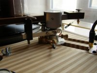
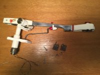
I think reducing carriage mass and simplifying the sliding mechanism is a good thing. I was thinking perhaps fixed rolling element with a sliding shaft attaching the cartridge a la ET arm but on the left side of the parallelogram might work? And it's easy to adjust stylus rake angle, SRA, in this scheme. Just thinking out loud...
One example is below, minus the pivot arm and air bearing, of course.
Interesting suggestion, Dd. I remember a similar diy arm made with a commercial recirculating bearing. Knowing them, and the small forces available for linear trackers I confess my doubts about its action, without a relevant inclination. If it works you could apply the parallelogram to the whole system, but the weight displacement would greatly increase the friction at the end of travel, moreover the hor. mass would be variable and relevant. Imho, of course
During the WE I would like to make parts to test the cart or parallelogram, but which parts? I involve you all in my doubts.
carlo
Walter - I'm studying the springs: hard work with few remaining neurons and zeroed memories of physics. But I still fear that the spring plays some role, with its potential energy.
Attachments
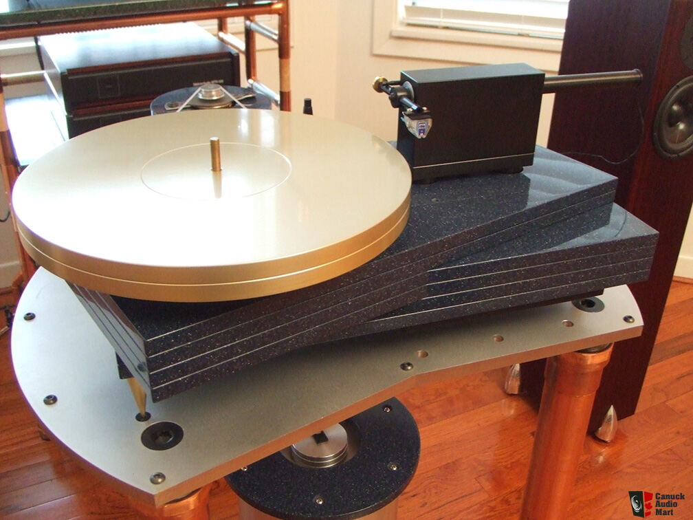
Directdriver, I like the arm in your picture. IMO, it is the best design among the air pump actions, and it seems as it doesn't need to be changed. The only thing I would change to make it more compact and user friendly, is to extend the arm itself. Also, possibly it will work with of much smaller diameter (and so, lighter) air guided horizontal tube (maybe made of arrow?- thy are rigid and light).
Nocdplz, my own experiments with spring counterbalance showed, that it works very well, tracking is excellent, better on big warps, than of regular arms. I can't put here the whole physical explanations, together with calculations, because they were published in Russian by one of prominent Soviet designers of hi-fi equipment, named Anatoliy Lihnicky. For me it is too complicated to put a translation here.With springs it is crucial to completely get rid of the counterweight, and not combine. Actually, combined arms will work, as gravitational arms do, but they will loose the main advantage in: descearing inertia, changing center of mass location (it is the main difference and advantage), and bearing chatter will come back too.
Spring has it's own resonance, but it can be easily suppressed, if needed.
Last edited:
Just think about travelling waves and spring reverb effect units used by musicians. Thorens spring suspension turntables have foam damping inserts, just as an example of damping. In our case a loose cotton wool insert would probably do.Spring has it's own resonance, but it can be easily suppressed, if needed.
@Carlo: referring to your drawings, it is not possible to support the balls on three points, because it prevents them rotating. You have to support them on their opposite poles.
Last edited:
Walter - Spring CW - I am also convinced that they work as, or even better than others: what does not convince me is that calculation of the eff. mass with that spreadsheet (but calculating by hand you get about the same results in much more time) applying a mass = 0 (2 grams was the minimum).
The result of 4.2 eff mass is really strange, if correct it is so low that an additional CW is needed to get a eff. mass usable with common cartridges.
Having to learn something unknown is one of the pleasures of building TA, perhaps the only real justification.
Icsazar - Strangely that of test works well: maybe not knowing the prohibition.
I'm joking - maybe balls roll on one point and a line: consider that in well born ones with V grooves they roll on 4 point.
carlo
lcsaszar, yes.Damping is easy.
Nocd, As to a counterweight again. Getting rid of it gives you the possibility to add that mass to your linear guide, to make it more rigid and sophisticated.
As to calculations, NIFFY posts are IMO almost perfect. That's the advantage of having mathematical mind, despite of us, artists😱
Nocd, As to a counterweight again. Getting rid of it gives you the possibility to add that mass to your linear guide, to make it more rigid and sophisticated.
As to calculations, NIFFY posts are IMO almost perfect. That's the advantage of having mathematical mind, despite of us, artists😱
Last edited:
Radial rail TA
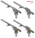
It's beginning to seem something that can be built. Two versions, one with the rail above the parallelogram (A) the second in the middle (B). I'll try the first just for the need of a stylus-plinth distance >40mm. Both can be converted with few mods to the spring-counterweight version.
I'll make some parts, starting from the parallelogram, to get clearer ideas. Will it work? Unfortunately to know this it must be done. and with tight tolerances.
ciao - carlo
Attachments
- Home
- Source & Line
- Analogue Source
- DIY linear tonearm