That supply looks OK for a standalone solution. If possible noise worries and concerns are going to cause loss of sleep, you could implement one of Mark Johnson's PO89ZB's (SMPS filter) into the build. Looks like the store has those in stock. Or the front end boards could be built straight into the F4, and simply powered from that +/- 24 volt supply. You probably wouldn't even need the F4's jfet input buffer. FE '22 should be able to drive the power MOSFETs gate capacitance. (?) Someone correct me if I'm wrong.. One less stage, maybe better SQ??
Thanks William
I forgot to write it but my intention were to use the nice PO89ZB's filter. I have a bunch of these at home, i even used some on my F3 power supplies.
My preamp will be a stand-alone solution since like many of us I have a bunch of power amps. I’m also building this together with a friend so that’s the reason I prefer using an external power source. No mains inside the preamp will be safer for him.
Eric
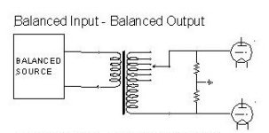
I want to use a balanced dac into a sowter 9336 attenuator transformer.This would output in balanced mode to the preamp. What
would be the value of the resistors used on the output of the transformer and does the midpoint of these resistors go to the virtual
ground of the preamp.
would be the value of the resistors used on the output of the transformer and does the midpoint of these resistors go to the virtual
ground of the preamp.
Attachments
Thanks for nice words, Koufax.
Yes, the layout is very tight. My alu chassis has dimensions 172mm x 291mm x 60mm only.
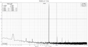
Last days I have done some distortion measurements with 10k load. Despite of the last quick test was good,
but not good enough. SMPS I used is better quality supply approved for medical applications
(Mean Well IRM-30-48ST 48V 630mA 30W) with input and output filter and ripple and noise max 300 mVpp.
But in the last spectrum were peaks with ominous frequencies 94 Hz, 188 Hz, 376 and so on.
Taking a 100 nF capacitor direcly to output screw terminal has calmed down all these intermodulation products.
It looks nicer now and sounds smoother.
Yes, the layout is very tight. My alu chassis has dimensions 172mm x 291mm x 60mm only.
Last days I have done some distortion measurements with 10k load. Despite of the last quick test was good,
but not good enough. SMPS I used is better quality supply approved for medical applications
(Mean Well IRM-30-48ST 48V 630mA 30W) with input and output filter and ripple and noise max 300 mVpp.
But in the last spectrum were peaks with ominous frequencies 94 Hz, 188 Hz, 376 and so on.
Taking a 100 nF capacitor direcly to output screw terminal has calmed down all these intermodulation products.
It looks nicer now and sounds smoother.
Attachments

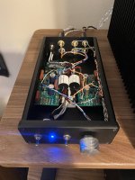
Thought I would share my FE build to use while I build my Balanced BBA3.
Used a small Hammond chassis with 48V SMPS. Also had some spare .33uf Sonicaps that had been sitting around for a long time I added as coupling caps.
Tons of gain for an F4 and sounds fantastic…. Need to hook up the second one now!
Used a small Hammond chassis with 48V SMPS. Also had some spare .33uf Sonicaps that had been sitting around for a long time I added as coupling caps.
Tons of gain for an F4 and sounds fantastic…. Need to hook up the second one now!
Attachments

Has anyone tried 2 of Mark's excellent SMPS filters, that is one "upstream" of each channel, instead of just one filter after the SMPS fedding both channels?
I know it sounds like overkill, but as it did make a difference on my VFET amp, admittely a very different animal, who knows...
Have fun
Claude
I know it sounds like overkill, but as it did make a difference on my VFET amp, admittely a very different animal, who knows...
Have fun
Claude
Yes several people have tried that experiment. Search the "PO89ZB" thread for the keywords "in series" and or "in cascade". Then decide whether their results on non-DIY-Front-End-2022 listening tests, insistently command you to immediately try it yourself.

Thanks for all the pics.
I’ve noticed that R10 in the above pic was a resistor but was then replaced by a wire, what’s the reason?
I’ve noticed that R10 in the above pic was a resistor but was then replaced by a wire, what’s the reason?
Awesome, thanks. I haven’t been following this thread closely, patiently waiting for the kit to be available 😀
I will use a 48v single supply.Can I just confirm that for an unbalanced input I connect -IN to ground of the input attenuator transformer and V- goes to the ground of the power amp.
Looking at these nice photos of nicely soldered JFet legs always reminds me of Revox and some of their top of the range R2R tape machines, where they used PCB headers for most of their transistors instead of soldering them directly.
I used the same technique a few years ago when building a Pearl I RIAA corrector with 2sk369 to great success. Still using it without a hiccup.
I tend to use IC sockets cut to the appropriate number of pins. Also allows me to try different JFETs in the respective position, or share rate JFETs between a number of builds 🙂
Regards, Claas
Regards, Claas
If I need -3dB gain how can I set Rf/Ri lower than 0.7 ?
Is it still stable if Av lower than 1 ?
Is it still stable if Av lower than 1 ?
- Home
- Amplifiers
- Pass Labs
- DIY Front End 2022