fact - some ppl are taking one Vbe as 600mV, some as 650mV, some as 700mV
ignoring that really depends of exact part and current trough, it is basic figure used as guide; tight guide, but not exact number carved in stone
Just now I measured the Vbe of the actual KSA992 (PNP transistor used in Nelson's Front End design), in my lab. Measurement conditions were:
- Vce = -20 volts
- Ice = -9.00 mA
- Air Temperature = 23 degrees C
- Number of parts tested = 10
630 mV , 629 , 626 , 631 , 629 , 625 , 628 , 627 , 628 , 628 mV { yes Vbe is a negative number for a PNP. no I didn't type it }
These data have a mean of Vbe = 628.1 mV and a standard deviation of 1.8 mV. Please feel free to use measured values of Vbe in your circuit analysis / hand calculations, and as a rough double-check of your simulation models.
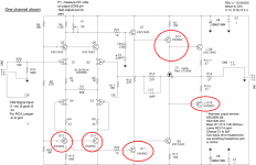
You now know that the drain current of input JFET device "Q1" is equal to (Vbe / R6) which is 924 microamperes, when Vbe=0.628 and R6=680. Of course a different value of R6 and/or a different value of Vbe will change this. If the tail current (supplied by Q3) turns out to be 3000 microamps, then 31% of it flows in the left leg of the differential pair (Q1), while 69% of it flows in the right leg of the differential pair (Q2). The diff pair isn't perfectly balanced, which might lead to an increase in second harmonic distortion.
Last edited:

A TO92 P-mosfet could be a future twist.
I couldn't help to think a full fets FE even the performance could be not as good as the original.
I couldn't help to think a full fets FE even the performance could be not as good as the original.
Hello wwwtttwww,
I have tried the full Fet-frontend as described in Nelson Pass' article (DIY Audio OpAmps) with Zetex ZVN3310/ZVP3310.
I wouldn't use the MosFets in the long tailed pair (first stage) anymore. The sound was slightly 'dark' or it seemed reduced in the
highs. Perhaps a result of the Ciss of 40 - 50 pF?
I prefer JFets in that position (LTP) - or a good pair of BJTs. It could be worth a try to test a P-channel JFet or a P-MosFet at the Q5 - position of the FE2022.
Try it.
Cheers
Dirk
Thank you all for your help!
:--))
Is there anybody who can measure or show his residual result made with AJ and using a sound card and Diana?
With normal values for R24 1k2?
:--))
Is there anybody who can measure or show his residual result made with AJ and using a sound card and Diana?
With normal values for R24 1k2?
I find pot to blur the mind, and bustin caps I stopped with back in the sandboxProbably an exercise reserved for the FAB elite… 😀

Sorry, my demand is in he wrong thread?Thank you all for your help!
:--))
Is there anybody who can measure or show his residual result made with AJ and using a sound card and Diana?
With normal values for R24 1k2?
:--))
That's what I really meant. Get the only BJT out of the picture.Hello wwwtttwww,
It could be worth a try to test a P-channel JFet or a P-MosFet at the Q5 - position of the FE2022.
Try it.
Cheers
Dirk
1. No BJT in signal pathreason?
2. To make a FE sound more and purer FET
3. To make R6 bigger to increase the gain of the first stage
4. Mr. Pass's famous amps don't use BJT as main amplifying components. Only use them as assistants, like cascade, CCS etc.
Last edited:
Any reason Not to use J111's?
I built this with parts on hand so J111 and ksa992 and as far as I can tell it works well
just had to change the CCS resistors to get 3ma / 9ma
This is neat! Thanks!
need to order parts and refresh how to measure Vp again
these were matched for IDSS only
I built this with parts on hand so J111 and ksa992 and as far as I can tell it works well
just had to change the CCS resistors to get 3ma / 9ma
This is neat! Thanks!
need to order parts and refresh how to measure Vp again
these were matched for IDSS only
Last edited:
I used MPSA18 in the signal path with great results. Also in liner power supply regulators. I see KSA992 is pretty good as well.
Sure they are great BJTs. But they sound BJT not FET at all.
I like the sound signature of FET, Jfet as input, Vfet as follower, Mosfet as Mu-Follower.
I will try Mosfet as VAS.
I like the sound signature of FET, Jfet as input, Vfet as follower, Mosfet as Mu-Follower.
I will try Mosfet as VAS.
I have never really played with Jfet vs bjt in low voltage signal path... let us know what your conclusion is.
It seems to me you'll have to discard all other benefits of one vs the other, and focus only on sound signature differences.
It seems to me you'll have to discard all other benefits of one vs the other, and focus only on sound signature differences.
I also have tried other devices for the Vas, including some cheap ones. It seems that the input pair are the dominant factor.
- Home
- Amplifiers
- Pass Labs
- DIY Front End 2022