Oh, com'on Jim, YOU can do that! 🙂))
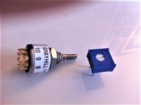
Brian, have a look at the dimensions of the switch / drawing from Grayhill, you will understand...
Even soldering Cat6 cable is quite a zen-experience, at least for me, and that is just 3 stereo inputs and one stereo output, all without ground, makes 8 tiny lugs to solder (with 2 inside at the middle!)...all packed within what is it, perhaps less than 1cm2?
Says IMHO a lot about our very modest Jim and his very real soldering skills
Attachments
Last edited:

Sorry to add to your tedium but I'm not following you....and definitely nothing personal inferred or intended. My position was simply that the 3.3uF WIMA cap that Papa quoted an actual part number for in the pdf in post #1 was non-stocked and, in post #216, I offered an alternate which was well stocked. At the time I was unsure whether the lead spacing on the PCB was 10 or 15mm. I later realised (posts 229 and 230) it was 15mm and offered a 15mm alternate on Digikey with good stock levels.Are you for real? derekr, pull you ears, why don't you read carefully🙂? The answeris in #312. It's nothing personal, but.......we overreacted. It started to turn really tedious. I apologise to everyone.
When you disagreed with me I pointed out that you were quoting lead spacings on a WIMA 4.3uF cap which was NOT the cap specified by Papa in the BOM. The specified WIMA 3.3uF/63V cap is available with lead spacing of either 10 or 15mm and the WIMA 4.3uF/63V cap you quoted is available, like you say in post #312, in lead spacing of 15 or 22mm. But 4.3uF/63V is not the cap in Papa's BOM so I thought you hadn't realised this - that's all I was saying.
If I've misunderstood your point please enlighten me and I'll pull the other ear when the penny drops!🙂
I picked that cap because it was good, available and cheap (at the time). Anything similar will be fine.
Next artwork iteration will have more lead space options.
Next artwork iteration will have more lead space options.
But sometimes more is fitting better......Best cap is no cap. Will fit any lead spacing.
🤓
Patrick
:--))
And no resistors, no transistors, and even no cables!Best cap is no cap. Will fit any lead spacing.
🤓
Patrick
The best sound of a pianno was direct! Pure analog, no A/D conversion, compression, etc 😉
Ok, a bit of a joke, but I'd rather use a discreet "opamp" like this one, with caps, in and out, than an opamp with no caps... 🙂
but I'd rather use a discreet "opamp" like this one, with caps, in and out, than an opamp with no caps...
I use a discrete opamp without signal coupling caps.
https://www.diyaudio.com/community/threads/the-xen-xelf-headphone-buffer.338371/post-5802879
https://www.diyaudio.com/community/...e-opamp-in-dip8-footprint.337484/post-5832263
🙂
Patrick
Transformers and capacitors joined in holy matrimony. Sounds good.Maybe an itegrated M2X? Hmmmm?
Can just use the M2 OPS :
https://www.diyaudio.com/community/...in-class-a-b-and-maybe-a-power-whammy.390636/
Patrick
https://www.diyaudio.com/community/...in-class-a-b-and-maybe-a-power-whammy.390636/
Patrick
best music is no music. Silence is golden. 🤣Best cap is no cap. Will fit any lead spacing.
🤓
Patrick
There is nothing to discredit. It is just a discrete opamp in its simplest form.
The circuit was published in the original article from Nelson.
https://www.passdiy.com/pdf/diyopamp.pdf
Adding input / output caps is just to make it easier to avoid hick-ups.
You can of course build this as posted, but you can also build it DC coupled.
As I have shown above, discrete opamp can be built fully DC coupled.
Caps always have sonic signature, Nelson said himself years ago.
I merely provide some advice how to eliminate them, and to ensure DC stability.
What I said was also mentioned by Nelson here :
https://www.diyaudio.com/community/threads/firstwatt-j2.151909/post-7256727
https://www.diyaudio.com/community/threads/firstwatt-j2.151909/post-7257152
Nelson himself also mentioned use of 2SK170 for the frontend,
So I again provide alternatively with 2SK209 which does not cost anywhere near as much.
Nothing I said contradicts what Nelson said elsewhere.
If you find any comments from me which are personal, offensive, or not fact based, please point out.
I would have no problem apologising if that should be the case.
If making suggestions to improve this is "discrediting", then I am guilty as charged.
I shall leave you to enjoy it as is, copied to the last details.
Cheers,
Patrick
Last edited:
'Watching' this thread, I've just checked the alert bell: it refers to a post (by Extreme_Boky) - dated 'tomorrow'. Que? 😵
Maybe this thread is "back from the future"? 🙂
P. S. The caps, I intend to use these ones:
On the downside, I have only two pieces, but then...
As it is going to be single in-single out, I will use some bipolar 4.7 uF for the grounded input. The output may "skip the cap" since it is going to be connected to a MoFo (which has its input cap already, I will just remove the bleeder resistor) and Voilà! 🙂
Attachments

- Home
- Amplifiers
- Pass Labs
- DIY Front End 2022