Hi @RickRay I created two pdf's for you "Wolverine IPS Only 30v Rail testing - with 57v full voltage rail components" and "Wolverine IPS Only 30v Rail testing - with 64v full voltage rail components" it looks like your 691uA is fine.I have 691uA across R6, so something above it must be wrong. I'll look at the divider R27 and R3 first, then may have to go to Q7.
Attachments

Yes, That's correct. I have updated the build guide. 🙂On to the EF3-3 boards. In test procedure 22.3 "If your Output Transistors are Not Installed". Am I correct that J103 should be installed?
Hi Guy's,
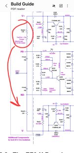
If anyone has noticed anything missing from the build guide or found any errors, please post them up so I can amend the guide ahead of the V5 board release.
Thanks
If anyone has noticed anything missing from the build guide or found any errors, please post them up so I can amend the guide ahead of the V5 board release.
Thanks
There's actually no ham caused if you leave J103 installed. It just forces the drivers to run in class AB rather then class A. But for consistency I'll add a note to ensure its removed.Might make sure it is mentioned to remove it when testing with outputs in the next section.
BTW, I have a 9.1k ohm resistor and a 5k pot for testing the EF3-3 in isolation. I'm guessing that will work just fine.
Hi Rick,On to the EF3-3 boards. In test procedure 22.3 "If your Output Transistors are Not Installed". Am I correct that J103 should be installed?
Yes, that is correct it connects the driver transistors to the output terminals and test points for testing purposes
- Dan
Just make sure this top combination of resistors match the bottom fix resistors before you start and the fix value resistor is ~12K. The 12K value is based on 64v rails so if your rails are lower the fixed value will be lower.BTW, I have a 9.1k ohm resistor and a 5k pot for testing the EF3-3 in isolation. I'm guessing that will work just fine.
Attachments
Can you use a +-30V bench supply to test the output boards in isolation? Or do you need to use the designed rail voltages?
30v rails are fine use a total of 5.7K for the resistors coming of each rail. This will ensure the same ~5mA is flowing through themReading the explanation above about the resistors, I'm guessing designed rail voltages.
I lke that a lot more. A little leary using an SMPS, no way to slowly ramp it up. Thanks for the heads-up!
I did not have a 5.7k resisitor and I upped the rail voltage to +-32V, limit of my supply, so I used 6.8k resistor for 4.7mA flowing through them. I only got 325mV across R111A and R111B, but the voltage did climb if I increased R109. I only went up to 350 and brought it back down. I also had to raise the current limiting to .5A on each rail to get it to start, but it did. Do you see any issues with my results?
Last edited:
BTW, might want to mention pinching Q103 between your fingers to see the bias lower, then raise when you take your fingers off.
No, Those results look ok. To ensure everything is working correctly you can put a small 100mVpp sine wave input in using a signal generator and check the output is a sine wave and ~95mVpp on your scope.Do you see any issues with my results?
- Home
- Amplifiers
- Solid State
- DIY Class A/B Amp The "Wolverine" build thread