-26VDC TP100 to spk gnd? That’s not even possible as those are the on the same bus. Recheck that. You should be testing for VDC from TP104 to TP100 (spk output and spk ground, essentially)
The TP105/6 readings are much better-still a bit low. Maybe due to low rail voltages or due to insufficient current draw through the IPS, The VAS CCS current (TP3/4) is really low at 104mV, is this perhaps due to an issue somewhere in the bias circuit or VAS circuit. Check the following are the correct parts and not installed backwards: Q10,11,12,13,14, 103 and 104.
When building I recall how easy it would be to confuse any of the small signal transistors.
Mainframe,
I have double checked all the transistors you listed. They are all correct.
I may have attached the offset negative to TP 104 instead of to output.
I will retest tomorrow.
Thanks
I have double checked all the transistors you listed. They are all correct.
I may have attached the offset negative to TP 104 instead of to output.
I will retest tomorrow.
Thanks
Read twice or until you understand it, then measure. Kind of like carpentry, measure twice, cut once.
Thanks for the help, I’m going to give this a try!Yes that's exactly what I had in mind if you choose to run one speaker protection board.
It you choose to run two, they can share a single 12v AC power supply. It will just be wired in parallel.

After confirming Q10,11,12,13,14, 103 and 104 are all correct I powered up today. All led's lit up.
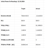
Observations are:
R111A to R111B [R109] was set to near 500ohms. When I powered up it went to .111mDCV.
I dialed R109 to the midpoint and never saw a change from .111mDCV.
TP3/TP4 is very low @91.1mDCV. Is that because I can't bias R109?
I've double checked all my parts with my first set of board builds, both ISP and Output boards worked correctly until I fried the output transistors due to not seating the output transistors correctly.
Appreciate any thoughts.
Attachments
I’ve got a working power supply… getting close!

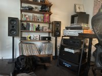
Hi @Mainframe @fireanimal here is my completed Wolverine now with added T Ground and Ground Lift (thanks Andy). Cobra PSU output ground leads L/R

 to the T Ground; T Ground wired to L/R to main board GND connections; T Ground wired to Ground Lift and from there to chassis. Amp remains completely silent, no hiss or hum whatsoever. Absolutely wonderful sound. Thanks again for all advice and help.
It’s alive! I’ve got a working amp here, woot. Sounds wonderful, bias is steady. 😊


Technical question: I have EF3-4 v3.9 boards. There are D105a - D105b, and D106a - D106b diodes rather than D105a and D106a as in EF3-3 or EF3-4 version 4 up. Why two pairs of diodes in series? Should I use only single diodes D105a and D106b and shorten the other two connections? These BAV21 diodes are across Q104 connecting emitter with collector.
Additional question: base resistors for power transistors are 2.2 ohm. I have plenty of high quality 2.4 ohm resistors. Would there be much difference in performance if I used 2.4 ohm resistors instead of 2.2 ohm in bases of power transistors?
Thank you,
Additional question: base resistors for power transistors are 2.2 ohm. I have plenty of high quality 2.4 ohm resistors. Would there be much difference in performance if I used 2.4 ohm resistors instead of 2.2 ohm in bases of power transistors?
Thank you,
Just got the wolverine connected to my main system. I’m speechless… what a wonderful thing. Thanks to all that have contributed to this project, I’m so grateful to have such a wonderful amp. Just in time for Christmas. Peace and love to everyone on this forum.
Attachments
Technical question: I have EF3-4 v3.9 boards. There are D105a - D105b, and D106a - D106b diodes rather than D105a and D106a as in EF3-3 or EF3-4 version 4 up. Why two pairs of diodes in series? Should I use only single diodes D105a and D106b and shorten the other two connections? These BAV21 diodes are across Q104 connecting emitter with collector.
Additional question: base resistors for power transistors are 2.2 ohm. I have plenty of high quality 2.4 ohm resistors. Would there be much difference in performance if I used 2.4 ohm resistors instead of 2.2 ohm in bases of power transistors?
Thank you,
1st GB BOM says wire link D105b and D106b - make sure you're using correct BOM and latest version. Also searching this thread for D105B returns the below:
Just a quick note. I don't want to cause any confusion but it is highly unlikely that you will need D105B & D106B.
Please see the build guide or my image below for the requirements.
Basically if you not running a 2 ohm load or you only install 2 output transistors you won't need these.
Not sure on your base resistor question but just gut feeling would be no, as you're 10% off spec at 2.4. Other more knowledgeable members may confirm if otherwise.
It's beyond me at this point - maybe try swapping in another one of you older known good IPS boards? might need a friendly local member to go over your boards? Good luck!After confirming Q10,11,12,13,14, 103 and 104 are all correct I powered up today. All led's lit up.
Observations are:
R111A to R111B [R109] was set to near 500ohms. When I powered up it went to .111mDCV.
I dialed R109 to the midpoint and never saw a change from .111mDCV.
TP3/TP4 is very low @91.1mDCV. Is that because I can't bias R109?
I've double checked all my parts with my first set of board builds, both ISP and Output boards worked correctly until I fried the output transistors due to not seating the output transistors correctly.
Appreciate any thoughts.
Hi Guys,
As we wrap up another exciting year with the Wolverine Project, I wanted to take a moment to express thanks to you all for support and enthusiasm towards this project. Whether you've contributed insights, shared feedback, or simply followed our progress, each of you has played an invaluable role in our journey.
Merry Christmas to all! I hope these festive days bring you warmth, joy, and the company of loved ones. May you create wonderful memories with friends and family. 😊🧑🎄😊🎁😊🧑🎄😊
Warm regards,
Stuart
Thanks Mainframe. I somehow missed this explanation reading documentation. My EF3-4 will be driving nominal 4 ohm speakers but the minimum impedance at some frequencies certainly will fall below 4 ohm, hopefully not too low so I'll use single diodes.1st GB BOM says wire link D105b and D106b - make sure you're using correct BOM and latest version. Also searching this thread for D105B returns the below:
Not sure on your base resistor question but just gut feeling would be no, as you're 10% off spec at 2.4. Other more knowledgeable members may confirm if otherwise.
When it comes to base resistor probably 2.2 ohm is the calculated/estimated optimum, however as calculations include eg hfe of transistors and these may vary quite substantially. Nevertheless, with bjts it's a rule of a thumb to use somewhat lower base resistor values to ensure that transistors are fully saturated if their Hfe values vary. So I'll use my ordinary 2.2 ohm 1W resistors rather than fancy low inductance low noise resistors of 10% higher values. With mosfets, especially lateral, gate resistors should be non-inductive to minimize chances for oscillation and somewhat higher resistor values than calculated optimum also help to achieve this.
Hi everyone,
Did anyone buy and use the new Modushop "Mini Dissipante 5U 400mm 10mm SILVER front panel - 2mm aluminium covers and 3mm rear panel" yet?
It seems to be compatible with the Wolverine heatsink drilling mod.
There are no pictures yet: https://modushop.biz/site/index.php?route=product/product&product_id=940
What I'm saying is that for 286.70€ for the enclosure, plus 73.20€ for the substitution Wolverine heatsinks, you get a Wolverine-ready case that's 36.60€ cheaper than the 396.50€ they ask for the Deluxe 5U enclosure (without the Wolverine heatsinks), even if you have to add an inner baseplate for the new case.
Furthermore, the Deluxe 5U seems to be out of stock, and this new case is available now. Someone should test it!
Furthermore, the Deluxe 5U seems to be out of stock, and this new case is available now. Someone should test it!
They are pretty much the same chassis, the main difference is the width which goes from 373 to 255. The prices you see are VAT included but assuming you order from Australia you have to deduct 22% 🙂 Here is a picture of the MiniDissipante 4U to give you an idea of how it can look like https://modushop.biz/site/index.php?route=product/product&product_id=877Hi everyone,
Did anyone buy and use the new Modushop "Mini Dissipante 5U 400mm 10mm SILVER front panel - 2mm aluminium covers and 3mm rear panel" yet?
It seems to be compatible with the Wolverine heatsink drilling mod.
There are no pictures yet: https://modushop.biz/site/index.php?route=product/product&product_id=940
I confirm this chassis can have the heatsinks drilled according to the Wolverine specs
Good morning from Crete.
I have a couple of KSC3503/KSA1381 pairs,
and I want to use them instead of
TTC004BQ/TTA004BQ recommended at +70v.
for Q101/Q102 and Q105/Q106,
the KSC3503/KSA1381 are VCEO= 300V
and TTC004BQ/TTA004BQ are VCEO = -160 V (min)
why? not recommended for +70v
Thanks
I have a couple of KSC3503/KSA1381 pairs,
and I want to use them instead of
TTC004BQ/TTA004BQ recommended at +70v.
for Q101/Q102 and Q105/Q106,
the KSC3503/KSA1381 are VCEO= 300V
and TTC004BQ/TTA004BQ are VCEO = -160 V (min)
why? not recommended for +70v
Thanks


- Home
- Amplifiers
- Solid State
- DIY Class A/B Amp The "Wolverine" build thread