Dopamine,
That is seriously nice chassis work! I chickened out and bought the diyaudio 5U steel case from Modushop.
I am using the diyaudio power supply boards which have a dedicated space for the snubber...so I can't help there. But now that I have a scope, I want to build that Quasimodo test board. Where did you get the test rig pub?
Best,
John

Slightly off topic - I really wish the chassis from modushop had the heatsinks fixed via screws accessible from the outside of the chassis I.e. screw heads between the heatsink fins in the wider spaced fin slots, this would make assembly much easier as you can install and remove amp channels without having to breakdown the entire chassis and use a mega long screw driver to install/remove the front panel. Not only did I encounter this, Daniel encountered this problem in his Wolverine assembly videos. I was closely tempted to drill new holes right through the heatsinks and side frames, then install rivnuts into the side frames in order to enable this functionality.
Don’t temp me Daniel, I’ll do it and post photos along with how much more accessible it makes the entire chassis 😂 I noticed working on the old parasound chassis I retrofit my EF3-3 build into vs the modushop chassis I did my EF3-4 build. The user friendliness was night and day with the parasound. Not to throw shade on modusounds chassis, they are very nice and I’m still very happy, but man would it have been easier if the heatsinks could be removed one at a time, externally rather than internally.
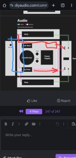
Why don't you think more in 3 dimensions and consider the z axis. Maybe run the output wires above the power wire.Hey all, I'd love some perspectives on wiring the 4-3 in a 4U case, any help or comments here would be greatly appreciated.
Please excuse my ruff sketch.
Attachments
I printed the PCB from the gerber files attached in the Quasimoto thread. I actually have a few extra. if you PM me your address I'll send you one. 👍Dopamine,
That is seriously nice chassis work! I chickened out and bought the diyaudio 5U steel case from Modushop.
I am using the diyaudio power supply boards which have a dedicated space for the snubber...so I can't help there. But now that I have a scope, I want to build that Quasimodo test board. Where did you get the test rig pub?
Best,
John
I concur with your frustrations. But I'm just happy I came across a photo of someone [maybe you?] using an extra-long screwdriver. That is now my prized tool of the year.Slightly off topic - I really wish the chassis from modushop had the heatsinks fixed via screws accessible from the outside of the chassis I.e. screw heads between the heatsink fins in the wider spaced fin slots, this would make assembly much easier as you can install and remove amp channels without having to breakdown the entire chassis and use a mega long screw driver to install/remove the front panel. Not only did I encounter this, Daniel encountered this problem in his Wolverine assembly videos. I was closely tempted to drill new holes right through the heatsinks and side frames, then install rivnuts into the side frames in order to enable this functionality.
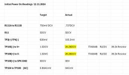
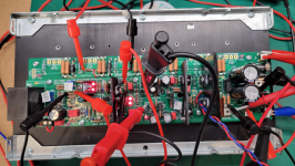
New month, new boards. I have built new ISP and output boards. I power up at 30DCV 0.3A on my Rigol. All Leds lite up. I adjusted R11 to 5DCV. But I'm getting some weird readings so I powered down.
This is what I'm seeing: see attachment.
TP105 and TP106 readings are my concern.
Having toasted my first set of boards, I want to take things slowly.
Appreciate getting this sorted. kolakidd has already been very helpful.
This is what I'm seeing: see attachment.
TP105 and TP106 readings are my concern.
Having toasted my first set of boards, I want to take things slowly.
Appreciate getting this sorted. kolakidd has already been very helpful.
Attachments
Assuming no board faults - that looks to me like you mistakenly measured TP105- to V-, instead of the target V+. And same reversal for the TP106+ measurement. Can you upload a picture of the board with red circles where you measured, separate photos for each of the 2x separate measurements.
Or there may be an issue in the IPS due to the VAS CCS current being low (106mV), but I'm not sure the CCS current is just low due to 30V test rails. Build guide seems to suggest even at 30V rails this should read close to 600-630mV
Or there may be an issue in the IPS due to the VAS CCS current being low (106mV), but I'm not sure the CCS current is just low due to 30V test rails. Build guide seems to suggest even at 30V rails this should read close to 600-630mV
Last edited:

yup thatl do itAren't you measuring on the wrong side of the resistor?
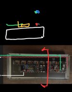
Getting ready to start the wiring, feeling a little nervous... this is the first amp I've wired. 😱
I created the wiring diagrams below and wanted to confirm with some more experienced builders if this is the correct understanding of how everything comes together. These do not reflect final wire routing.
Did I make any errors here? Any help greatly appreciated.


I created the wiring diagrams below and wanted to confirm with some more experienced builders if this is the correct understanding of how everything comes together. These do not reflect final wire routing.
Did I make any errors here? Any help greatly appreciated.
Everything looks like your on the right track.
Personally I wouldn't run my amplifier output wires past the transformer. I'd make another speaker protection board so you don't have to have your amplifier output crossing your power wires. Other than that if you want to run one speaker protection board. Maybe move it to the output end of you chassis. You maybe then able to route you output wires so they don't cross your AC power wires.
Personally I wouldn't run my amplifier output wires past the transformer. I'd make another speaker protection board so you don't have to have your amplifier output crossing your power wires. Other than that if you want to run one speaker protection board. Maybe move it to the output end of you chassis. You maybe then able to route you output wires so they don't cross your AC power wires.
Attachments
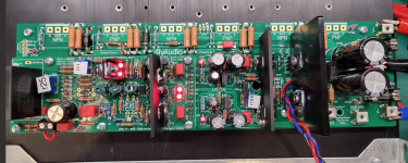
Second round of initial readings using a DC regulated supply at 30DCV and .3AYep. Sure am.
Thanks a bunch.
I resolved the readings for TP106 and TP105.
New questions.
1. I could not increase the voltage on R111A to R111B beyond the .737DCV reading, no matter how far I turned the pot.
2. TP3 - TP4 also didn't change from 105.7mV, significantly below the target of 630mV. Is this because I couldn't increase R109 voltage?
3. Shouldn't TP106 show a [-] reading?
4. I also could not change the offset measure using R25.
Biggest question is why no movement of R109. On my first round of boards, I had no trouble getting to 1.1DCV
Attachments
Thanks Stuart, that feedback is very helpful. Another speaker protect board would be the best solution. I'm not sure how I would power two speaker protect boards with my transfo, could I do both from a single 12v ac secodary?Everything looks like your on the right track.
Personally I wouldn't run my amplifier output wires past the transformer. I'd make another speaker protection board so you don't have to have your amplifier output crossing your power wires. Other than that if you want to run one speaker protection board. Maybe move it to the output end of you chassis. You maybe then able to route you output wires so they don't cross your AC power wires.
I did a little more sketching, the below isn't as elegant but would avoid crossing the power wires with the audio signal I think.
Any thougts?
- Home
- Amplifiers
- Solid State
- DIY Class A/B Amp The "Wolverine" build thread