After reviewing point 17.1 G those measurements look okIs this expected behavior? I'm using the TTC and TTA transistors.

What parts did you use at Q101/102All working fine with Cobra and 71v. 0.5A fuses intact. Everything measures good - only anomaly is TP105 to rail is 1.721, TP106 to rail is -1.858. I will install the outputs and proceed. Thanks to everyone for help, @mainframe99 and @stuartmp
What I found with the cobra and I can’t really explain fully - sometimes powering up with a cobra would blow 0.5A fuses (when testing without output transistors installed) and I think even 2A once (with output transistors installed) even if there is nothing wrong with the boards.All working fine with Cobra and 71v. 0.5A fuses intact. Everything measures good - only anomaly is TP105 to rail is 1.721, TP106 to rail is -1.858. I will install the outputs and proceed. Thanks to everyone for help, @mainframe99 and @stuartmp
The only thing I could put this down to was inrush current due to what I can only assume is the resting state of the BJTs - what I mean by that is sometimes when you perform test step 16.3
In a lot of cases with a perfectly healthy board you can perform test 16.3 and get 0 ohms / dead short for a about 500 milliseconds and then the resistance will skyrocket to 3-16k ohms and then onto 300k ohms and then onto 5-6 megohms. (Your mileage may vary but this is a ballpark figure) I have seen this on every board I have done.
I found if I didn’t perform 16.3 and hold the meter on for a decent 30 seconds for all the steps to get the measured resistance as high as possible ie draining all the stray shorts out of the board, connecting a big *** SMPS would blow the fuses instantly, then I’d replace them and try again and all was fine.
TLDR
Not saying you should just keep installing fuses if your fuses blow! I’m saying when measuring resistances at step 16.3 , V+ / V- / GND / OUTPUT, hold your meter on all points for a decent amount of time to get the highest measured resistance possible and drain all stray voltages that are holding semis open!!
The standard Toshiba semis as listed in the BOM. I think I know what you mean about 16.3....it takes a long while to stabilise. Really interesting what you said about fuses, as I was absolutely sure I had the correct ones! I realise now why two LEDs didn't light on the IPS, guess the fuses went before the voltage went high enough. I'll report back when outputs installed. Fingers crossed!What parts did you use at Q101/102
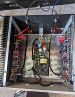
Well, I got there in the end! Here is my completed Wolverine. Clean and simple - no soft start (Cobra has a soft start anyway), ground lift, T ground or protection circuits, thought I would see how it sounded just as it is. And the verdict? Astonishing. Completely silent - no hum or hiss. I was prepared to be underwhelmed, but boy was I wrong. This is better than any other amp I have heard, and with power to spare. I have learnt so much along the way, much of it from this forum. I would like to thank everyone involved with the project, and specifically @fireanimal , @stuartmp , @danieljw , @mainframe99 and @bullittstang , together with Sami from microaudio@aol.com and Gianluca at Modushop. It's been quite a journey.....now what to build next?!
Attachments
Hi @plasticator - Great to hear you have completed and are enjoying the amplifier.
Let me start by saying from an mains electrical safety standpoint you have done all you are required to. The chassis is connected to mains earth and will protect anyone touching the chassis from electric shock, should an internal failure occur. I also note - that the connection you have from the chassis bond point to the SMPS heatsink is only necessary if you have installed the SMPS on non conductive (i.e.. nylon) standoffs.
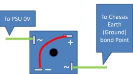
I'll tell you what to build next, and at your earliest convenience. A ground lift (1). This is in the interest of protecting your nice amp, SMPS, and rare outputs. I have attached 2 ideal schematics for you to follow (pick one). The T-GND section is not necessary but is a preferred option. You may also use the simpler (but for noise reasons with SMPS, not preferred) Bridge Rectifier arrangement as shown in "How to wire-up an Audio Amplifier" (2), distributed with the wolverine document package. Both attached and cited below. This also applies to Linear power supplies IMO.
Here's why:
Lets say you have either
** I will admit, I'm aware the AC line input and DC load output are isolated + opto-isolated and this shouldn't occur, but the SMPS feedback control sure doesn't appear to enjoy having its own output fed back into its input**

If the 0V line of the SMPS is connected to the chassis via a ground lift, the fault path is as follows, and the protection in the SMPS will activate much faster, resulting less damage done, maybe even none. Cobra Rail protection is fast.

Once you have installed the ground lift, before connecting back to mains, I urge you to perform a resistance test (not beep/bell) from each output transistor leg to the chassis. If anything is reading a low resistance say under 10k ohms, you may have found a potential future short.
1. https://sound-au.com/earthing.htm - Earthing (Grounding) Your Hi-Fi - Rod Elliot (ESP) 1999.
2.https://hifisonix.com/wp-content/uploads/2019/02/Ground-Loops.pdf - How to wire-up an Audio Amplifier - hifisonix - Andrew C Russell 2019.
Let me start by saying from an mains electrical safety standpoint you have done all you are required to. The chassis is connected to mains earth and will protect anyone touching the chassis from electric shock, should an internal failure occur. I also note - that the connection you have from the chassis bond point to the SMPS heatsink is only necessary if you have installed the SMPS on non conductive (i.e.. nylon) standoffs.
I'll tell you what to build next, and at your earliest convenience. A ground lift (1). This is in the interest of protecting your nice amp, SMPS, and rare outputs. I have attached 2 ideal schematics for you to follow (pick one). The T-GND section is not necessary but is a preferred option. You may also use the simpler (but for noise reasons with SMPS, not preferred) Bridge Rectifier arrangement as shown in "How to wire-up an Audio Amplifier" (2), distributed with the wolverine document package. Both attached and cited below. This also applies to Linear power supplies IMO.
Here's why:
Lets say you have either
- Stray swarf steel/alu wedged between an output transistor and the heatsink, piercing the thermal pad not enough to make a short straight away during testing and commissioning, but may work its way through after multiple thermal cycles and short the transistor collector to the heatsink,
- An internal DC rail cables insulation eventually wears out and shorts to chassis,
- There are many scenarios, but basically a full DC rail, or to a lesser extent a speaker output finds a path to the chassis
** I will admit, I'm aware the AC line input and DC load output are isolated + opto-isolated and this shouldn't occur, but the SMPS feedback control sure doesn't appear to enjoy having its own output fed back into its input**
If the 0V line of the SMPS is connected to the chassis via a ground lift, the fault path is as follows, and the protection in the SMPS will activate much faster, resulting less damage done, maybe even none. Cobra Rail protection is fast.
Once you have installed the ground lift, before connecting back to mains, I urge you to perform a resistance test (not beep/bell) from each output transistor leg to the chassis. If anything is reading a low resistance say under 10k ohms, you may have found a potential future short.
1. https://sound-au.com/earthing.htm - Earthing (Grounding) Your Hi-Fi - Rod Elliot (ESP) 1999.
2.https://hifisonix.com/wp-content/uploads/2019/02/Ground-Loops.pdf - How to wire-up an Audio Amplifier - hifisonix - Andrew C Russell 2019.
Attachments

I'll add to this step, it may be necessary to unplug the amp boards from the cobra, to avoid measuring the loop through the SMPS output and the 10R in the ground lift.Once you have installed the ground lift, before connecting back to mains, I urge you to perform a resistance test (not beep/bell) from each output transistor leg to the chassis. If anything is reading a low resistance say under 10k ohms, you may have found a potential future short.
Hi @mainframe99 thanks very much indeed for your helpful and insightful reply. I was happy re electrical safety aspect (and glad you agree). The Cobra sits directly on the chassis but is heavily anodised so electrically the connection is the 6 x M3 bolts attaching it. I guessed it was overkill to add a bolt + star washer earth directly to it but it made me feel more comfortable. I had thought the main application of the T ground was helping sort out ground hum/noise problems and the like, so I thought I would try without (and it sounds really clean). But your argument for adding a T ground to protect the amp boards and the Cobra is very compelling - thanks a lot, I will definitely follow that up.Let me start by saying from an mains electrical safety standpoint you have done all you are required to. The chassis is connected to mains earth and will protect anyone touching the chassis from electric shock, should an internal failure occur. I also note - that the connection you have from the chassis bond point to the SMPS heatsink is only necessary if you have installed the SMPS on non conductive (i.e.. nylon) standoffs
KEC KTA1837/KTC4783
available at https://us.profusion.uk/int/audio/transist/driver-transistors,
Anyone tried them?
available at https://us.profusion.uk/int/audio/transist/driver-transistors,
Anyone tried them?
I'm sure they just got licensed from Toshiba , got the original lithography . Most likely the same part , right down to the topology.KEC KTA1837/KTC4783
edit - possible improvements.
OS
I'm watching these as they aren't in stock in Europe yet, wanting to buy a small pile..KEC KTA1837/KTC4783
available at https://us.profusion.uk/int/audio/transist/driver-transistors,
Anyone tried them?
I've bought the UTC complementary 1837/4793 some years ago from profusion, and they work perfect and never had any issues. I do not see or measure any changes in the amps where trached the original Toshiba 1837/4793 for the UTC. Hopefully the KEC will perform equally
They are in stock now.
Of course onsemi mje1503x series are available drivers but out of 40+ pairs I have I got only ONE matched npn-pnp pair.
Of course onsemi mje1503x series are available drivers but out of 40+ pairs I have I got only ONE matched npn-pnp pair.
Look to be on par with the existing UTC parts they stock. Data sheets only tiny differences are in the hFE. Certainly better than the EVVO variant DIGIKEY are stocking.KEC KTA1837/KTC4783
available at https://us.profusion.uk/int/audio/transist/driver-transistors,
Anyone tried them?
Hello,
I am close to finishing building a Wolverine with EF3-4 from the 4th group buy. Everything is going well this far but I have a question about C125 and C126. In earlier versions they weren't in the schematic. Will it be any significant difference if I skip these capacitors? For the moment I do not have the SMD capcitors for C121 and C122 but have the through hole versions that mounts in the same place as C125 and C126.
I am close to finishing building a Wolverine with EF3-4 from the 4th group buy. Everything is going well this far but I have a question about C125 and C126. In earlier versions they weren't in the schematic. Will it be any significant difference if I skip these capacitors? For the moment I do not have the SMD capcitors for C121 and C122 but have the through hole versions that mounts in the same place as C125 and C126.
They are not fully complementary, something like a beta of 500 and 130 between the devices if I remember correctly. You might have offset problems, but that just a guess🙂Hello,
I have some analog devices mat02/mat03
can i to use instead of bc550/560
Thanks
I am no expert but the MAT02/03 Cob value is 23pF compared with 6 pF for the BC550/560 "C" grade.Hello,
I have some analog devices mat02/mat03
can i to use instead of bc550/560
Thanks
This and its much larger die/dice are potentially the reasons why the MAT02/03 is slower than the BC550/560 by approximately 100 MHz.
Despite the metal can it is also about 1 dB noisier per the datasheet.
Without testing it is hard to say but you might experience reduced performance and stability with the MAT02/03.
Might be best to stick with the recommended BC550/560 (C) but if you want to experiment let us all know how you go.
- Dan
Hi guys,
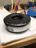
UPS lost my Toroidy transformers. Toroidy filed a claim and sent me a new pair which arrived today. I got the appropriate size metal plate and two neoprene insulating pads for each transformer. However, they do not come with the 1/4" bolts necessary to tie them to the chassis.
Time for another clueless question: does it matter what material the bolt is made from? Will a common magnetic steel bolt passing through the core of the transformer affect its performance?
Many thanks,
John
Attachments
- Home
- Amplifiers
- Solid State
- DIY Class A/B Amp The "Wolverine" build thread