https://www.diyaudio.com/community/threads/matching-transistors-measuring-the-results.307138/How can I get this circuit, understand how to build it and learn how to use it? I know one of the guys on this forum has circuit boards.
John

Hey Jeff!
Thank you very much for the link.
John, it is a very simply circuit that relies on the basic concept of a differential pair - exactly how it is used in an amplifier. Therefore, you match the parts in the circuit they will be used in.
The jig has sections for NPN and PNP, independent of each other. I normally run it with bipolar supplies of 11 VDC to be close to test conditions used by the manufacturer (10 VDC), the tail current is selectable. You could increase the voltage to what your circuit sees taking care you stay within the limits of the tester's parts and thermal limits. The exact current doesn't need to be exact, just close to what your circuit uses and stable. It uses a constant current source to that end. The one important thing is to use resistors very close in value. I used 0.1% resistors with a low temperature coefficient and match those ('cause I'm nuts and I can). SO the important parts are the 100R pair and 10K pair for each polarity. That and you have to use good sockets, not from Ebay or AliExpress. I tried cheap sockets because people were making kits. They are impossible to use and cause trouble. The LEDs are a 3mm, standard efficiency red type. It fits through the hole of the TO-126 transistors used in the CCS.
Make the two parts touch and cover them with foam. Cover the entire jig with a box and allow the parts to stabilize thermally. I presort the parts with a normal tester, but you'll find parts that measured the same may be far apart on the jig. Temperature is the big factor.
-Chris
Cool looking IPS !! , no problem with any reasonable voltage.Running them at 15,2V currently because I had no 12V zeners in stock.
12-33V is the wide range you can use. The resistor between the led ccs's might have to be increased for >20V.
Spooky input pairs are fully "hidden" behind the regulators ... "ghost LTP's" . My new Spook has to be 12V to also run the
op-amp servo , yours can be any voltage.
OS
Last edited:
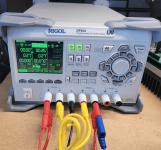
I replaced the DC supply with the Rigol DP832. It has a much better manual and user interface, at least for me.Can I ask what function does this board provide? see attached photo.
thanks
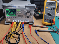
Finally got the right cables to wire this up for initial testing. The supply is set for series.
I have set channels 1 & 2 in series at 15DCV and .27 Amps with a current limit of .30 amps. On/off sync is enabled on.
Believe I have the wiring correct. But when I turn both channels on I don't get any voltage shown on the Rigol or as measured by my DMM.
Both channels separately work fine. Been You tubing and manual crawling all afternoon. I'm at the outer limits of my experience and I'm hoping I've missed something simple? I'm wondering if I need to invest in a DC Electronic Load Tester to ensure my settings are correct before I attach my circuit board for testing.
Attachments
The ground lead to the amp shouldn't be connected to the earth connector on the supply. It should go to the yellow lead.
Thanks. I clearly need it. If not for lack of trying. I've been going around in circles, barking up trees all day.
Leave the earth ground on the supply disconnected. The black lead needs to connect between the yellow lead on the supply and the ground connection on the amp board.
It's uploading nowThanks. I clearly need it. If not for lack of trying. I've been going around in circles, barking up trees all day.
Stuart,
I got it.
For the initial test of the wolverine board, I will change the voltage to 30DCV and to 0.3A with a 0.3A current limit for both channels.
Getting close now.
Thanks.
I got it.
For the initial test of the wolverine board, I will change the voltage to 30DCV and to 0.3A with a 0.3A current limit for both channels.
Getting close now.
Thanks.
@chiptec.
You do better change the RED 4mm-lead at the verry right (connecting the minus-pole to minus of theVOM with a blue croco clip )
to a BLUE lead. Helps even the most experienced specialist to more clarity on the workbench
Red always +
black always null
blue - rev. to black
green or green/yelow to the chassis , if necessary for safety
i hope not to have started a new dicussion.....
ingo
Ok guys, I fnally got my IPS Boards done except for a pair of resistors that I forgot to order. I am going to proceed to building the EF3-4 boards. Then I'll do a clean-up order with Mouser to order any additional parts I overlooked.

Ok guys, I fnally got my IPS Boards done except for a pair of resistors that I forgot to order. I am going to proceed to building the EF3-4 boards. Then I'll do a clean-up order with Mouser to order any additional parts I overlooked.View attachment 1362501
Wow, good eye mainframe99! I filled it and checked the rest....all good. Just completed visa and jumpers on the EF3-4 boards. I'm now fitting the boards to the diyaudio 5U heat sinks to determine what holes I have to drill ab
Ordered boards paid on fri i have my boards on Monday WHAT SERVICE THAT IS HOW IT IS DONE MY HAT IS OFF TO STUART AND JJS THANK YOU I AM ALREADY PLACING PARTS THIS IS 2ND BUILD I LISTEN TO MY EF-3 EVERY DAY BEST AMP EVER!!!!!!!!!!
thanks to all the help along the way, I just finished the initial power up on my first channel.
I used a Rigol DC supply to fix V @ 30V DC and amps at 0.3A
Happy to report nothing burned.
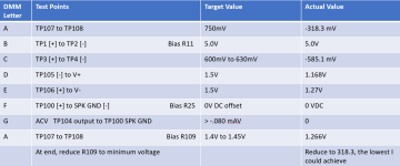
I would like some oversight on my metrics as shown below.
When I first turned the power on TP107 to TP108 showed -318.3mV.
When I dialed up R109 to the max the highest voltage I achieved was 1.266DCV
Is this because I'm not delivering full power? Or is something amiss?
I used a Rigol DC supply to fix V @ 30V DC and amps at 0.3A
Happy to report nothing burned.
I would like some oversight on my metrics as shown below.
When I first turned the power on TP107 to TP108 showed -318.3mV.
When I dialed up R109 to the max the highest voltage I achieved was 1.266DCV
Is this because I'm not delivering full power? Or is something amiss?
Attachments
Hi Guys,
I ordered two Audio Grade 500VA transformers with 2x 50 Volt secondaries from Toroidy for a dual mono power supply. That got me thinking about wire size for the Wolverine so I searched this thread and didn't see anything. How can I determine the correct wire size for the internal wiring of this amplifier for use in the U.S. (nominal 120V mains)? Would you use the same gauge wire as the secondaries on the transformers?
Thanks,
John
Hang on a sec.thanks to all the help along the way, I just finished the initial power up on my first channel.
I used a Rigol DC supply to fix V @ 30V DC and amps at 0.3A
Happy to report nothing burned.
I would like some oversight on my metrics as shown below.
When I first turned the power on TP107 to TP108 showed -318.3mV.
When I dialed up R109 to the max the highest voltage I achieved was 1.266DCV
Is this because I'm not delivering full power? Or is something amiss?
You say you got NEGATIVE 318mV, then dialed it up to positive 1.26V ?
- Home
- Amplifiers
- Solid State
- DIY Class A/B Amp The "Wolverine" build thread