Hi jminassi,
This is housekeeping stuff. So, you can use a switcher from AliExpress, 120 VAC to 12 VDC, the cheap ones run at around 150 KHz, so well above the audio range. You can filter the output as well if you are concerned, put a metal plate between it and the world, but you may not need to. It's a very cheap fix.
Most suppliers sell little switching supplies cheaply as well, Digikey and Mouser do for example.

Hi Mahtew,my question is more towards lack of space between components
resistors and diodes are touching capacitors
placing them at the bottom side would partially fix this. but BOM shows different components values depending on mounting style (parallel vs perpendicular) and this might be connected with how air cools components (my assumption)
so don't know how different placement might impact my build 🙂
Have a close look at the Vbe multiplier update section in the latest build guide it goes over the options for this section.
Is there any reason not to get capacitors which fit the layout here?
More doesn't necessarily mean better results.
- Dan
(The following for EF3-4 group buy 4)hi, i have a question about placing resistors and diodes around C102-3, C106-7 caps
i have a lot of 270uF 12.5mm dia caps for that positions, but if i'll use them, there is not enough space for R101/4, D111/112, D113/114, D105a/106a and maybe R102/103. I plan to mount those elements at the bottom side of the board.
Board will be mounted perpendicular to the heatsink. boards ef3-3 and ef3-4
are there any caveats that should taken into account?
You need to buy 10mm parts for C123, 124, 125 and 126 anyway (as 12.5mm will ABSOLUTELY not fit here) so I wouldn't. By using a physically wider part at C102, 103, 106 and 107 you create the risk of shorting a component to a filled solder pad and parts being unnecessarily lifted from the board and wobbly. You also don't need exotics here, if that's you're angle.
You can do what you're suggesting, but I'm recommending you don't and just get all 10mm parts so you can complete C102, 103, 106, 107, 123, 124, 125 and 126 competently.
I have completed a set of EF3-4 and tested them in the perpendicular arrangement (using driver auxiliary heatsink and remote mounting of Q103) so feel free to ask any more questions. Remember in this arrangement to use the EF3-3 parts for R105, 106, 107 and Rcc.
Last edited:
Hi Guys,
I just spent a couple of hours matching Q1, Q2 BJTs. I bought 50 and left them on the paper strip they were supplied on. I used my DCA75 Pro to match them on Vbe and hFE. Then I pumped the results into a spreadsheet and did the sort first on Vbe and then on hFE within Vbe. All I can say is those devices must be super sensitive to their environment. I never touched any of them directly. After attaching the DUT to the Peak Atlas meter I covered the device with a bowl to keep any air currents away. But the third digit in both the Vbe and hFE was not repeatable in any meaningful way. I'm disappointed that I could not get more repeatable results. Am I worried that this will impact the performance of the Wolverine. Not really. But using recently produced Onsemi devices makes me question the utility of attempting to measure these devices. The Vbe was very close...all measured between .765 and .767. The hFE was more variable.
Thoughts?
John
I actually got a couple of exact matches......but I could not repeat it. Generally the third digit on the hFE reading would change by 1 or 2. As I said Vbe was very tight. hFE jumped around. The meter pulses the device with 5 mA, and I suppose that is enough to cause the readings to fluctuate when repeated.
1-2 PPM , at most. Unless you don't even match. Wolverine global NFB will swamp all but the grossest of mismatches.Thoughts?
But we are "fanatics" , right !!
OS
yeah man, jobs good. onto the next stepI actually got a couple of exact matches......but I could not repeat it. Generally the third digit on the hFE reading would change by 1 or 2. As I said Vbe was very tight. hFE jumped around. The meter pulses the device with 5 mA, and I suppose that is enough to cause the readings to fluctuate when repeated.
Take a look here: https://www.arrow.com/en/products/vof-40c-s12/cui-incThanks asuslover. If I do that, how do you propose I power the Diyaudio Speaker Protection Board? Use a separate small transformer? It requires 12VDC to power the relays.
John
thanks for responses
i simply have more than 100 dia.12.5mm 220uF and 270uF caps from different vendors ... and scratching my head where to use them 🙂
but understood that using them with Wolverine might produce more issues than needed
probably will have to consult Q103 location (probably on main hatsing between q110 and q112, but that question will come up ...much much later)
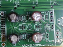
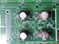
but hey, checked tha 12.5dia "might (almost)" fit ARCWELDER ops, so not everything is lost 🙂
thanks!
what's the latest build guide? mine is v41 not covering v4GB rev.Hi Mahtew,
Have a close look at the Vbe multiplier update section in the latest build guide it goes over the options for this section.
Is there any reason not to get capacitors which fit the layout here?
More doesn't necessarily mean better results.
- Dan
i simply have more than 100 dia.12.5mm 220uF and 270uF caps from different vendors ... and scratching my head where to use them 🙂
but understood that using them with Wolverine might produce more issues than needed
was thinking about using Kapton tape for isolation, but will use 10mm dia for safety 🙂You can do what you're suggesting, but I'm recommending you don't and just get all 10mm parts so you can complete C102, 103, 106, 107, 123, 124, 125 and 126 competently.
I have completed a set of EF3-4 and tested them in the perpendicular arrangement (using driver auxiliary heatsink and remote mounting of Q103) so feel free to ask any more questions. Remember in this arrangement to use the EF3-3 parts for R105, 106, 107 and Rcc.
probably will have to consult Q103 location (probably on main hatsing between q110 and q112, but that question will come up ...much much later)
but hey, checked tha 12.5dia "might (almost)" fit ARCWELDER ops, so not everything is lost 🙂
thanks!
Attachments
Take a look here: https://www.arrow.com/en/products/vof-40c-s12/cui-inc
Thanks, I'll check it out.
John
Hi jminassi,
Don't worry about VBE, match beta.
There is a jig I designed for this purpose, given to this community years ago. At least three PCBs have been designed for it over time. This will give you repeatable results and extremely tight matches. It places the pair in a long tailed pair configuration with current source. The parts end up at the exact same temperature (required for matching), simple circuit. Your meter is used as a null device in the mV range.
Hi jminassi,
Don't worry about VBE, match beta.
There is a jig I designed for this purpose, given to this community years ago. At least three PCBs have been designed for it over time. This will give you repeatable results and extremely tight matches. It places the pair in a long tailed pair configuration with current source. The parts end up at the exact same temperature (required for matching), simple circuit. Your meter is used as a null device in the mV range.
How can I get this circuit, understand how to build it and learn how to use it? I know one of the guys on this forum has circuit boards.
John
Hi John,
I think there is a thread on it. I showed it in an Adcom GFA-565 thread (I think) and members took off with it.
-Chris
I think there is a thread on it. I showed it in an Adcom GFA-565 thread (I think) and members took off with it.
-Chris
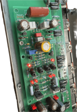
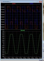
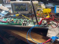
"Spooky" ?? Ahh... with the led Hawksford VAS. It will have quite a different character. clips nice ,My Spooky frontend for the EF3 OPS is alive.
but is 5-10ppm thd. "party amp"....
What voltage did you run the regulators at ?
OS
Attachments
- Home
- Amplifiers
- Solid State
- DIY Class A/B Amp The "Wolverine" build thread