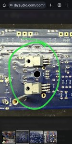
I rechecked Q101 and Q102. NPN/PNP is correct. They are 2SC3503E and 2SA1381E
The voltage on TP06 to ground is ~10V and for TP05 is ~19V
I have tested Q103 & Q104, and rechecked NPN vs PNP
My PSU is on 31V, but it is only drawing 23mA
It's the same for both boards.
The voltage on TP06 to ground is ~10V and for TP05 is ~19V
I have tested Q103 & Q104, and rechecked NPN vs PNP
My PSU is on 31V, but it is only drawing 23mA
It's the same for both boards.
Probably not relevant to the fault but just in case - Do you have 9.1k resistor paralleled with R17 for testing ?


Check settings of your bench-PSU negative rail for right voltage and no current limiting.
In #4070 you reported measuring the correct voltage over Q102 (TP106 to neg rail - 1.2V)
This together with reported values in #4081 (TP106 to ground 10 V) points to a problem with the negative rail
In #4070 you reported measuring the correct voltage over Q102 (TP106 to neg rail - 1.2V)
This together with reported values in #4081 (TP106 to ground 10 V) points to a problem with the negative rail
Yes, checked that by putting it on another bench supply.
Also swapped out Q107 and Q108.
I'm hoping to feel really stupid at some point.🤣
Also swapped out Q107 and Q108.
I'm hoping to feel really stupid at some point.🤣
This problem is really vexing, thanks for the suggestions so far... beats staring at the board. To summarise so far:
I am currently trying to test the boards with a 30V supply. It’s a Korad KA3005D
The issue:
D108 doesn’t light up on either of my two boards
The status:
What I have done:
I am currently trying to test the boards with a 30V supply. It’s a Korad KA3005D
The issue:
D108 doesn’t light up on either of my two boards
The status:
- The voltage across R111A and R111b is just below 800mv (750-790)
- TP-105 to pos power rail is 1.2V (TP-105 (DMM -) and the positive power rail connection)
- TP-106 to neg power rail is 1.2V (TP-106 (DMM +) and the negative probe on the negative rail)
- TP106 to GND is roughly at ±19V
- TP105 to GND is roughly ±-9V
- V+ to GNB is ± +20V
- V- to GND is ± -10V
- The board pulls around 23mA from the PSU
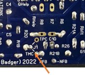
Jumper and R17 9k are installed, and input is shorted. - R109 is set to 500R across pins 1&2
What I have done:
- Switched out all leds and tested them after replacing them
- Switched out:
- Q103
- Q107, Q108
- Took out and tested Q101, Q102, Q104, Q105, Q106
- Changed PSU leads and tested using an older bench PSU.

I don't think your power supply has a negative supply. The + and - are regular positive voltage and the ground connection is safety ground.
It is ± +30V, -30V now.
Other:
Voltage to rail between D107 and RLED1 is 1.2V (TP05 1.2V)
Voltage to rail between D108 and RLED2 is 1.3V(TP06 1.3V)
I shifted to Testing at 20V
0V to between TP05 and RLED1 is 1.2V
0V to between RLED1 and D107 is 18V
0V to between TP06 and RLED2 is 18.6V
0V to between RLED2 and D108 is 18.9V!
The Red Led is still not lit, but I think I must review everything again.
Strange indeed, definitely something wrong with the rails.
Sticking with 30V rails for now
Check rail fuses
Check continuity between ground and all transistor legs
What are you getting between TP3 and TP4
Might pay to fill the unused pads on R7 and R8
Might need to switch to testing in isolation
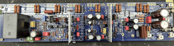
Stuart has provided a testing IPS at 30V (with 64V components) and EF3-X in the dropbox and build guide
Sticking with 30V rails for now
Check rail fuses
Check continuity between ground and all transistor legs
What are you getting between TP3 and TP4
Might pay to fill the unused pads on R7 and R8
Might need to switch to testing in isolation
Stuart has provided a testing IPS at 30V (with 64V components) and EF3-X in the dropbox and build guide
Last edited:
I fyou have the correct voltage going to each rail, but are getting a low postive voltage on the negative rail, check your pre-drivers and drivers. I had a problem just like this one on my AB100 amplifier.
Yeah something might be pulling a rail down.
I would print out / digitally mark up the schematic. Leave your DMM- on the amp GND and probe and markup the schematic with all the voltages you are getting.
If using 30V rails I would expect TP105 to GND would be ~ +27V while TP106 would be ~ -27V.
I would print out / digitally mark up the schematic. Leave your DMM- on the amp GND and probe and markup the schematic with all the voltages you are getting.
If using 30V rails I would expect TP105 to GND would be ~ +27V while TP106 would be ~ -27V.
Yes, I think both those things are the next step, isolation testing and step by step checking.
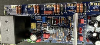
The Jumper is always required, it must be installed EF3-3 EF3-4 does not matter.I Can't help with your current issues. But I'm wondering why you didn't install the J1 jumper. I'm early days in a EF-3, so maybe it's not needed in EF-4?
I believe it's installed top sideBut I'm wondering why you didn't install the J1 jumper
Attachments
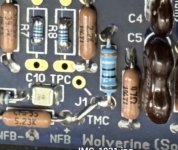
Just so I'm clear: wrap a thin wire around a bolt from the CCS heat sink to G2 and solder to the board?I have tested both ways and it makes no difference in this case, but depending on the wire used, it can improve stability.
- Home
- Amplifiers
- Solid State
- DIY Class A/B Amp The "Wolverine" build thread