Check out this board GFlo
https://www.diyaudio.com/community/threads/lt4320-based-active-rectifier.336572/post-6233338
https://www.diyaudio.com/community/threads/lt4320-based-active-rectifier.336572/post-6233338

Thanks alot guys,
I got my hands on a set of LT4320 based PSU boards from @fireanimal already, thanks again for that!
You are right @OmeEd, I still need a utility board for protection, inrush limit, etc. On that side note, your design looks great, I really like the microcontroller based setup and the quality of life functions that come with it, any chance that you wanna release it for external use and got a spare PCB?
Thanks for the valueable info about the DC, I would have totally missed that!
Thank you. As there where others who asked the same question I will offer some insight on my position regarding sharing the design. I do like to share it with the community, but what you see above is a prototype, and being a prototype it needed some rework on the PCB to make it behave the way I intended. It works great but releasing it in this state would require to much support from my side, costing more time then I am willing to spend. Another matter being that while working on the software and building the board in to my amp I got some idea's that I like to incorporate before ordering the next PCB revision. There is no time path and no guaranty that I will even finish it. I am retired and only spend time on electronics when I feel like it. Summer is on it's way, I will often be in the garden, might go on a road trip, or even go sailing.
Hey, dont worry I totally understand that and I think everyone else will too. Hopefully summer will be here soon without melting instantly in 35°c outside after all that bad weather...
I got another question regarding the BOM before I hopefully can start ordering parts soon, if there are more values to choose from, like for C1, C9, C101, C102, etc, is there anywhere an indication of what to choose exactly? I couldnt find anything in the build guide, hope I didnt miss anything.
I got another question regarding the BOM before I hopefully can start ordering parts soon, if there are more values to choose from, like for C1, C9, C101, C102, etc, is there anywhere an indication of what to choose exactly? I couldnt find anything in the build guide, hope I didnt miss anything.
Hi Andy, I am also in the latest group buy for a pair of EF3-4 boards. I would like to purchase a set of the finished heatsinks from you, for postage to the UK. Be grateful if you could send me details or PM me. Thanks v muchI have had a bunch of inquiries on heatsinks, the new heatsinks are now available for those who were looking. These are flat black anodized, driver heatsink tapped, and pins installed. I currently have the CCS/VAS and predriver heatsinks on hand for EF3-4 boards, and the driver heatsinks arriving shortly for the EF3-3 boards. These heatsinks will only fit GB1-GB3 boards.
The new group buy boards will be using updated pin heatsinks, and whoever is interested in those can you let me know, so I have a rough idea on order qty.
I also received a bulk order of CPF emitter resistors. They are 500mOhm 1% 150ppm, they will be lead formed and ready to install.
Heatsinks
EF3-3 $65 - 2 CCS/VAS | 2 Predriver | 2 Driver
EF3-4 $40 - 2 CCS/VAS | 2 Predriver | No Driver Heatsink
Vishay Emitter Resistors
EF3-3 $70 Set of 24
EF3-4 $90 Set of 32
Hey guys, i just finished my build.
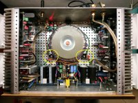
I made my own custom PSU in dual mono with 2x500VA 45Vrms toroidy transformer so about 62VDC after diode bridge.
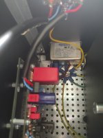
Upper board include AC precharge, DC voltage detection, speaker SSR relay, capactor discharge, trigger input, speaker current sensor. I use an stm32G474 and all protections are manage with peripherals interconnection and not through SW routine.
I have button inputs but finally not use it, also heatsink temperature measurement which where not mounted on the pictures.
I planned to have a 14segments displays controlled by an i2c bus.
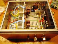
Then i wanted a vintage look. I bought VU meters and tried to use current sensors to calculate instantaneous power but at low level, current is too small for my sensors.
At the moment there is nothing on the front pannel.
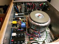
i tried different transformer position. i first staked them on top of each other but each transformer transfered noise to both channel. additionaly when i had a channel with low noise the other one had maximal noise.
With final setup left transformer only affect left channel and same for right channel.
here are pictures of the amp:


I made my own custom PSU in dual mono with 2x500VA 45Vrms toroidy transformer so about 62VDC after diode bridge.
Upper board include AC precharge, DC voltage detection, speaker SSR relay, capactor discharge, trigger input, speaker current sensor. I use an stm32G474 and all protections are manage with peripherals interconnection and not through SW routine.
I have button inputs but finally not use it, also heatsink temperature measurement which where not mounted on the pictures.
I planned to have a 14segments displays controlled by an i2c bus.
Then i wanted a vintage look. I bought VU meters and tried to use current sensors to calculate instantaneous power but at low level, current is too small for my sensors.
At the moment there is nothing on the front pannel.
i tried different transformer position. i first staked them on top of each other but each transformer transfered noise to both channel. additionaly when i had a channel with low noise the other one had maximal noise.
With final setup left transformer only affect left channel and same for right channel.
here are pictures of the amp:
Attachments
Hi @TeteDampoulei tried different transformer position. i first staked them on top of each other but each transformer transfered noise to both channel. additionaly when i had a channel with low noise the other one had maximal noise.
With final setup left transformer only affect left channel and same for right channel.
There is no doubt that you have put a massive effort into this Amplifier. It looks great.
If I may make a few suggestions to try and work out where the noise is coming from.
1. Try connecting the amplifier power rails to and external Lab power supply and see if the noise remains.
2. If you have no noise this is a good thing and I would then suggest moving all your existing power supply out and away from the chassis especially the sensitive input stage.
If you can run it with the power supply external to the chassis and there's no noise this proves your power supply is not the issue.
3. If all that works I would suggest reinstalling everything in the chassis but this time around rotate it all 180°so the transformers are at the output end of the amplifier.
Good luck.
Attachments

Hi @stuartmp,
Thank you for these advices.
Maybe i have not been clear. At the moment and in the actual setup i was able to reduce noise for each channel at a level that is hard to hear with "headphone trick" by rotating transformer. So the noise was clearly linked to the transformer and the distance with input stage. I am talking about 50Hz noise.
I did test with transformer outside the box and there was no noise.
I have been following this guide that suggest that input stage is next to transformer:
https://www.diyaudio.com/community/attachments/dual-mono-pdf.1035911/
I agree with you and for those who have not build the amp yet i would also recommend to try to put the input stage far from the transformer.
Finally with no source connected to the amplifier, it is perfectly silent. With my preamp connected i get a small "white noise" that i can only hear when i put my hears very close to the tweeter of the speaker. It is fixed and does not change with preamp level.
I am very satisfied with the result.
Hi.Thank you for these advices.
Maybe i have not been clear. At the moment and in the actual setup i was able to reduce noise for each channel at a level that is hard to hear with "headphone trick" by rotating transformer. So the noise was clearly linked to the transformer and the distance with input stage. I am talking about 50Hz noise.
I did test with transformer outside the box and there was no noise.
I have been following this guide that suggest that input stage is next to transformer:
https://www.diyaudio.com/community/attachments/dual-mono-pdf.1035911/
I agree with you and for those who have not build the amp yet i would also recommend to try to put the input stage far from the transformer.
Finally with no source connected to the amplifier, it is perfectly silent. With my preamp connected i get a small "white noise" that i can only hear when i put my hears very close to the tweeter of the speaker. It is fixed and does not change with preamp level.
I am very satisfied with the result.
do you have install any of this? inside your amp or preamp for each channel ?
my input RCA are about 6-7 cm distance from trafos..
No hiss no noise at all.
Attachments
Last edited:
Great work 👏 👍 👌Hey guys, i just finished my build.
I made my own custom PSU in dual mono with 2x500VA 45Vrms toroidy transformer so about 62VDC after diode bridge.
Upper board include AC precharge, DC voltage detection, speaker SSR relay, capactor discharge, trigger input, speaker current sensor. I use an stm32G474 and all protections are manage with peripherals interconnection and not through SW routine.
I have button inputs but finally not use it, also heatsink temperature measurement which where not mounted on the pictures.
I planned to have a 14segments displays controlled by an i2c bus.
Then i wanted a vintage look. I bought VU meters and tried to use current sensors to calculate instantaneous power but at low level, current is too small for my sensors.
At the moment there is nothing on the front pannel.
i tried different transformer position. i first staked them on top of each other but each transformer transfered noise to both channel. additionaly when i had a channel with low noise the other one had maximal noise.
With final setup left transformer only affect left channel and same for right channel.
here are pictures of the amp:
View attachment 1320081View attachment 1320083View attachment 1320084View attachment 1320085View attachment 1320087View attachment 1320088View attachment 1320089View attachment 1320090View attachment 1320091View attachment 1320092View attachment 1320093
@Nikos
Yes i have.
I guess you get different result because the position of the transformer in your amplifier is a bit different. The center of the transformer is aligned with the input stage heatsink in your config. In my config it is aligned with input stage connector.
This could make a difference.

Yes i have.
I guess you get different result because the position of the transformer in your amplifier is a bit different. The center of the transformer is aligned with the input stage heatsink in your config. In my config it is aligned with input stage connector.
This could make a difference.
Hmm ...maybe.This could make a difference.
can you stack the PSU boards? parallel to the front of the box with different directions ? if the high of the box its too high also ...so the trafos came closer to front of the box...
Fantastic, so sorry for the misunderstanding I'm glad that you are happy with the results. I hope that you now have time for plenty of listening pleasure.Finally with no source connected to the amplifier, it is perfectly silent. With my preamp connected i get a small "white noise" that i can only hear when i put my hears very close to the tweeter of the speaker. It is fixed and does not change with preamp level.
I am very satisfied with the result.

I get your point but the board where not designed to be stacked due to ground lifter integration and control board on top.
The only possiblity with my boards is 180° rotation but as i said i am curently satisfied with this layout.
Thank you for sharing your solution that will for sure help other builders.
The only possiblity with my boards is 180° rotation but as i said i am curently satisfied with this layout.
Thank you for sharing your solution that will for sure help other builders.
After a couple revisions the Input Buffer is now finished and ready to go.

Switchable between unbalanced and balanced input. Balanced input has built in attenuation of 6dB to gain match with the Wolverine IPS and Unbalanced connections.
On Board Regulators, with filtering so both linear or SMPS can be used. Input volage should be between +-20VDC and +-24VDC.
On EF3-4 it will bolt right up beside the IPS, EF3-3 can be mounted remotely.

Very low idle noise on both Balanced and Unbalanced inputs <1uV 20-22.4k
The issue I have found in a lot of testing is that unless the Source is isolated, and not mains powered there is a lot of loop noise. This is a measurement of the Wolverine connected to a D90 III DAC. This is a typical noise floor I see under these conditions.

And now the same DAC connected with a Balanced Connection to the Buffer, then the Wolverine.

Here are some 1 Watt SNR measurements for comparison. Wolverine, Buffer Unbalanced, Buffer Balanced.
Wolverine Only

Buffer Unbalanced

Buffer Balanced

And here are some measurements of just the Buffer in isolation.
Gain and Phase Balanced

Gain and Phase UnBalanced

IMD Tests


I will start a dedicated Preorder Thread for those interested.
Switchable between unbalanced and balanced input. Balanced input has built in attenuation of 6dB to gain match with the Wolverine IPS and Unbalanced connections.
On Board Regulators, with filtering so both linear or SMPS can be used. Input volage should be between +-20VDC and +-24VDC.
On EF3-4 it will bolt right up beside the IPS, EF3-3 can be mounted remotely.
Very low idle noise on both Balanced and Unbalanced inputs <1uV 20-22.4k
The issue I have found in a lot of testing is that unless the Source is isolated, and not mains powered there is a lot of loop noise. This is a measurement of the Wolverine connected to a D90 III DAC. This is a typical noise floor I see under these conditions.
And now the same DAC connected with a Balanced Connection to the Buffer, then the Wolverine.
Here are some 1 Watt SNR measurements for comparison. Wolverine, Buffer Unbalanced, Buffer Balanced.
Wolverine Only
Buffer Unbalanced
Buffer Balanced
And here are some measurements of just the Buffer in isolation.
Gain and Phase Balanced
Gain and Phase UnBalanced
IMD Tests
I will start a dedicated Preorder Thread for those interested.
This is amazing. Fitting it on the unused EF3-4 space is 😍
- Home
- Amplifiers
- Solid State
- DIY Class A/B Amp The "Wolverine" build thread