Thanks Andy, perfect, sorry didn't realize they'd already been posted, almost 200 pages now 😵

For the best cooling it should be upside down, don't you think so?
Kinda why I was asking, I think the heatsink itself is symmetrical i.e. you just flippy 180deg as you need. You could have both sides outputs up, down, or one up & one down
Hi Guy's
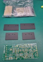
Just a quick update. The production of the 4th GB boards is complete.

They will soon be dispatched to @jjs, @fireanimal and myself.
I'll update you all once they arrive.
Just a quick update. The production of the 4th GB boards is complete.
They will soon be dispatched to @jjs, @fireanimal and myself.
I'll update you all once they arrive.
stuartmp said:
"""Transient Response: Linear power supplies with sufficient bulk capacitance excel at providing a stable voltage even during sudden changes in power demand. This capacitance acts as a buffer, ensuring that the power supply can handle transients well."""
When we say sufficient capacity...would like to define a range of sizes in capacities ? for this amp the Wolverine.
Thanks.
Which way is up?
But yeah, as it has already been pointed out we usually try to center everything on the heatsinks and not shift them up or down @mainframe99
Exactly! 👍I think the heatsink itself is symmetrical i.e. you just flippy 180deg as you need. You could have both sides outputs up, down, or one up & one down
The only thing I should add to my admittedly flippant comment is...
With the newer chassis that come with the "full surround" rails/mounts, if folks want to alter "up or down" based on preference, they'll need to note the placement of the captured (don't know if that's the correct word) nuts on the rails. Those are used for attaching the back panel. It's only a few bolts to remove / change it if you get it "wrong", but best to do it right the first time.
Sorry for the delay I've been working on a response for you.When we say sufficient capacity...would like to define a range of sizes in capacities ? for this amp the Wolverine.
Thanks.
When we talk about sufficient capacitance for the rails of a high-performance Class AB amplifier, such as the Wolverine, it’s crucial to understand the factors that influence the required amount.
For this specific amplifier, the Wolverine, a recommended starting point is 20,000µF per rail, as shown in the power supply schematic in the Dropbox folder. However, this is just a baseline, and the actual requirement can vary based on several factors:
1. Transformer VA Rating: A higher VA rating provides more current and is more capable of maintaining voltage under load, thus potentially requiring less capacitance to smooth out the ripple since the power supply is more robust or stiff.
2. Speaker Impedance: If you are driving lower impedance speakers (e.g., 4 ohms), the current demand on the power supply increases, which may necessitate more capacitance to ensure stable operation under dynamic load conditions.
3. Rail Voltage Drop: The tolerance to rail voltage drop under load is another consideration. Higher capacitance can help reduce voltage sag during high power output, ensuring consistent performance.
So you need to consider what rail voltage drop you are prepared to tolerate.
### Sample Calculation for Voltage Drop
To estimate the voltage drop when driving 80 watts RMS into 4 ohms:
#### Step 1: Calculate the RMS current
Given:
P = I^2 x R
Rearranging to solve for I:
I = sqrt(P / R)
Substitute the given values:
I = sqrt(80W/4Ω)
I = approx 4.47A
#### Step 2: Calculate the Peak-to-Peak Ripple Voltage
Assuming a full-wave bridge rectifier and capacitive filtering, the main frequency matters (50Hz or 60Hz).
The peak-to-peak ripple voltage V_{ripple(p-p) can be approximated using:
V_{ripple(p-p) = I_load / (f x C)
Where:
- I_load is the load current (4.47 A)
- f is the ripple frequency (2 times the mains frequency because of full-wave rectification)
- C is the capacitance in farads
#### For a 50Hz mains frequency (ripple frequency f = 100 Hz
V_ripple(p-p) = 4.47A / (100Hz x 0.02F)
V_{ripple(p-p) = 4.47 / 2 = 2.235V
#### For a 60Hz mains frequency (ripple frequency f = 120 Hz
V_{ripple(p-p) = 4.47A / (120Hz x 0.02F)
V_{ripple(p-p) = 4.47/2.4 approx 1.8625V
### Summary
So, with 20,000µF per rail, you can expect approximately:
- A 2.235V peak-to-peak ripple voltage at 100Hz (50Hz mains frequency)
- A 1.8625V peak-to-peak ripple voltage at 120Hz (60Hz mains frequency)
So, while 20,000µF per rail is a good starting point, you may need to adjust this value upwards depending on your specific transformer VA size, the impedance of your speakers, and your acceptable range of rail voltage drop under load conditions you willing to accept.
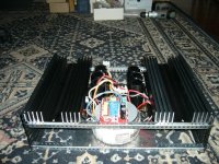
Outputs down, it makes some difference. The best way with passive cooling is the fins up like on the attached photo.Kinda why I was asking, I think the heatsink itself is symmetrical i.e. you just flippy 180deg as you need. You could have both sides outputs up, down, or one up & one down
Attachments
No one is saying to go against the conventions of convection... 🙂
I was making a joke that seems to have not landed.
Fixed... except for Aussies...

I was making a joke that seems to have not landed.
Fixed... except for Aussies...
Ive used them both up and down, on the bench and in my builds. Didnt notice much difference either way to be honest
No there isn'tI have the boars from 1st group buy, is there any sonic differences with the latest version?
I thought it was funny.I was making a joke that seems to have not landed.
Hi folks,
I purchased the third group buy EFX-4 boards. I am getting ready to order parts. There is a new BOM, and I'm aware that the fourth group buy boards have been modified slightly.
Questions:
1) Which BOM should I be looking at?
2) There are several values of capacitance specified for C1 and for C115 and C117. What impact, if any, does selecting one value over the other have?
Many thanks,
John
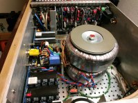
What I noticed in my construction case...is that how big the heatsink plays a role. There is a temperature difference which tends to appear as time goes by..... one thing is for sure that placing the transistors on the lower side of the heatsink is the best option for cooling....but in this way you will not have the two inputs or outputs facing the same side.Didnt notice much difference either way to be honest
Attachments
1. At the bottom of the Schematic it has the version of pcb that it relates to.1) Which BOM should I be looking at?
2) There are several values of capacitance specified for C1 and for C115 and C117. What impact, if any, does selecting one value over the other have?
2. C115 and C117. Basically larger capacitance values are better but it also depends on your budget and supplier availability.
2. For values of C1 please search this thread as there has been plenty of discussion on the topic. Also search the word input impedance.
If you still have a question please post again.
What I noticed in my construction case...is that how big the heatsink plays a role.
I noticed your comment about the temperature issues. It seems like the heatsinks you're using are undersized to startwith. If you had larger or more adequate heatsinks, you likely wouldn't experience those higher temperatures than you expected. This also means you could mount your transistors in either orientation (up or down) without worrying about unbalanced temperature rises.
- Home
- Amplifiers
- Solid State
- DIY Class A/B Amp The "Wolverine" build thread