Just had my first read through of the build guide. It's lovely. I used to write documentation for the software I wrote and I know writing a user guide can be as much hard work as the thing it's describing. Well done to everyone who had a hand in its creation.

I agree with yours comments. We described the same problem with different words... That's why i put external Pwm fan on heatsinks. Now i run the amplifier at 2x59V on limits (speakers 4Ω 300W) with thermal safety ...not above temp 45 C on heatsinks 27.5cm x 16cm x5 cm with temp room also 30C...with this way keeps the bias also rock steady at 40-45mv.(not transferred extra heat inside the box and minimize the bias).I noticed your comment about the temperature issues. It seems like the heatsinks you're using are undersized to startwith. If you had larger or more adequate heatsinks, you likely wouldn't experience those higher temperatures than you expected. This also means you could mount your transistors in either orientation (up or down) without worrying about unbalanced temperature
Attachments
Last edited:
I've been playing around with the new hypex SMPS with promising results. Unlike older hypex models, this one includes a host of convenience features such as PFC, 130kHz switching, 12V trigger inputs, inputs for both momentary and latching power-on/off switches, 5V standby always-on power supply, outputs for standby and run LEDs among more.
Noise floor - wolverine - 1 channel - in complete chassis. 96khz sampling

Same again with 192khz sampling - I have yet to get my head around getting 384khz sampling to work on windows and REW. The 16khz is USB packet noise, I have proven this.

1khz, 5W into 8ohm. 96khz sampling. (96 is more stable, 192 often hiccups). Reminder - visible harmonics are from my DAC

I'm certain the 50 and 3rd noise is from the incoming AC line or the AC line rectifier and using shielding could have some improvement. Starting to look good for 95dB+ sens speakers.
Noise floor - wolverine - 1 channel - in complete chassis. 96khz sampling
Same again with 192khz sampling - I have yet to get my head around getting 384khz sampling to work on windows and REW. The 16khz is USB packet noise, I have proven this.
1khz, 5W into 8ohm. 96khz sampling. (96 is more stable, 192 often hiccups). Reminder - visible harmonics are from my DAC
I'm certain the 50 and 3rd noise is from the incoming AC line or the AC line rectifier and using shielding could have some improvement. Starting to look good for 95dB+ sens speakers.
@mainframe99 if you have calibrated your ADC voltages, do you mind changing the scale to V, or dBV so we can see the actual level please. Also are you using any other filtering or is that SMPS right to the Wolverine?
Yes, overkill. Don't bother with the 3k on the wolverine. Unless you planned on running 2x4 ohm loads at 400W continuously, somehow.
Last edited:
@fireanimal here, I think your cobra measurement still has it beat (was it in case or on bench only?). Still, a nice alternative in the new hypex.
 Oh and no filtering, SMPS straight to Wolverine. Cant seem to figure out that 3rd/150.. might be our nasty mains really clipped tops.
Last edited:
Something maybe limiting to your Wolverine, though a single channel, may be the maximum continuous power that this model could provide: 100w...only.
(From PSU datasheet)
Kal.
Hi Guy's
Just a quick update,
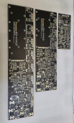
The boards have arrived and they look great.
Please give us a few days to prepare for shipping, then you should receive your paypal request.
Not long now guy's thanks for your patience and support of the Wolverine project.
Just a quick update,
The boards have arrived and they look great.
Please give us a few days to prepare for shipping, then you should receive your paypal request.
Not long now guy's thanks for your patience and support of the Wolverine project.
Attachments
The SMD cap, underneath the electrolytic, or underside of board? So there are now 6 caps total here?
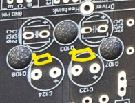
The SMD caps are located on the underside of the board as shown below.The SMD cap, underneath the electrolytic, or underside of board? So there are now 6 caps total here?
The idea is.
1. If you don't like SMD soldering then just install the 2 THT electrolytic capacitors and the two THT film caps, all top side.
2. If your happy to solder SMD then install the 4 THT electronic capacitors top side and the 2 SMD film capacitors on the underside.
Hope that helps.
Attachments
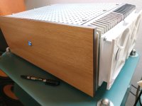
The microprocessor based upgrade of my amplifier as described in message #3622 is now done and build into the amplifier. I am very satisfied with the result. The fact that the amplifier is now well secured, switches on and off discreetly, and the luxury that this takes place automatically, contributes to the quality experience.
I also took the opportunity to give the amplifier it's own name, Wolverine translates in Dutch and German language to respectively Veelvraat and Vielfraß (eats lots), both have a negative connotation within their language area. This amplifier deserves a name that reflects her quality, so I now call her Apotheosis, meaning; elevated to divine level.


I also took the opportunity to give the amplifier it's own name, Wolverine translates in Dutch and German language to respectively Veelvraat and Vielfraß (eats lots), both have a negative connotation within their language area. This amplifier deserves a name that reflects her quality, so I now call her Apotheosis, meaning; elevated to divine level.
Hello together,
so far Ive had a look at quite a few toroid power supply related guides already. There are really alot of great sources on here and out there generally. But now im stuck with the specific implementation, I dont feel like I can design one myself yet so my question now is, can anyone recommend a PCB design or similar that takes into account following points:
-multiple capacitors per rail (aiming at 2x10000µF per rail)
-the option for a snubber circuit (dont know if I really need it, but its nice to have the option)
-and considerations regarding ground impedance coupling (like mentioned in pages 42-48 in https://hifisonix.com/wp-content/uploads/2019/02/Ground-Loops.pdf) especially for multiple capacitors per rail. Thats probably the thing that Im most interested in currently, I can see how it works for 1 cap per rail with the T junction, but no idea what would be ideal for multiple caps and especially PCBs featuring multiple caps. According to the guide it seems to be of crucial importance.
You will need an inrush limiting device to start up the toroidal. And since Germany is crowded with solar panels you might also need a DC-blocker to keep the toroidal quiet.
You will need an inrush limiting device to start up the toroidal. And since Germany is crowded with solar panels you might also need a DC-blocker to keep the toroidal quiet.
How much DC do you guys normally see on your line?
Enough to make it audible, especial during dusk and dawn, and minor hum during daytime, at night its clean.
A simple DC-blocker consisting of a halfway shorted bridge rectifier bypassed with a set electrolytic capacitors neutralizes the problem, so must be less then 1.2 Volt.
A simple DC-blocker consisting of a halfway shorted bridge rectifier bypassed with a set electrolytic capacitors neutralizes the problem, so must be less then 1.2 Volt.
- Home
- Amplifiers
- Solid State
- DIY Class A/B Amp The "Wolverine" build thread