Oh okay. So doing monoblocks with a single antek trafo? Or are those cases big enough for two of them in one case? Thanks for the reply, really new to all of this, and I don’t want to get the boards without knowing the total cost!If you are poor/cheap (me). I have 2 cases like the "dissipante" 5U X 300mm for 80$ (broken EBAY amps). They came with 2 working 400W SMPS !!
Nope - A stereo pair on ONE 500VA. For bench testing (Fireanimal) ... yes 800-1KVA. In the real world , 500VA is quite sufficient for a 150W X 2 amp.
My HK680 just has @ 350VA + 4 X 6800u = 105W/ch. My amp is 500VA + 6 X 6800u , should give me a healthy 150W X2.
I have one of the Wolverine boards running a sub on a 200VA trafo = 200+W. Runs nice an' cool on one of those EBAY case heatsinks.
Really nice builds here ... but most are obscene overkill (compared to OEM).
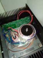
Really pleased with the Antek trafo . A 500VA Antek would equal a 600+ VA OEM.
OS
My HK680 just has @ 350VA + 4 X 6800u = 105W/ch. My amp is 500VA + 6 X 6800u , should give me a healthy 150W X2.
I have one of the Wolverine boards running a sub on a 200VA trafo = 200+W. Runs nice an' cool on one of those EBAY case heatsinks.
Really nice builds here ... but most are obscene overkill (compared to OEM).
Really pleased with the Antek trafo . A 500VA Antek would equal a 600+ VA OEM.
OS
Nah , I don't think 2 500's (5.25") would fit. (below) Antek 800 would (6.5") ....
Ebay has one more left for 28$ - https://www.ebay.com/itm/165843672091
Heatsinks are bigger than the DIYA 300mm , but less internal room. 3 pair wolverine just fits !!
Someone else could also go cheap. Spend the $$ on more electronics (800VA, better caps ,protection circuit).
PS - little trafo is for my fancy Arduino protection system.
OS
Attachments
Thanks man. Just pulled the trigger on it. I should have probably gotten the boards before the case 😅Ebay has one more left for 28$ - https://www.ebay.com/itm/165843672091
Heatsinks are bigger than the DIYA 300mm , but less internal room. 3 pair wolverine just fits !!
I’ll probably use it for this, or maybe ill try and build and Alpha Nirvana instead.
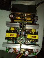
It actually works (the amp) , has 2 >300W SMPS's in it . +/- 45V and a trigger port that raises to voltage to +/- 58V.
Old school SMPS , but well built with PFC. They used these amps for whole school PA systems...
Edit - OR , use the 2 included (working) 300W SMPS's - real cheap !!
OS
Old school SMPS , but well built with PFC. They used these amps for whole school PA systems...
Heatsinks would work well with class A , choose the wolverine !! 800VA + big caps = very compact - VERY powerful bada$$ amp !Alpha Nirvana
Edit - OR , use the 2 included (working) 300W SMPS's - real cheap !!
OS
Man, I wish big toroids weren't so expensive to get here. I have a couple EI's, but they all have multiple (5+) lower power outputs as they came from multi channel amps. Hard to find big stereo power amps, faulty, here. Have 1 nice massive 1200VA toroid, but i think it was like 42VDC x2, so what like 36VAC? not much use for it, yet.
Not bothered, the cobra -s2 and hypex smps both sound amazing in my wolverine('s) anyway, I have no want to switch them, just be nice to put the toroid to work somewhere.
Not bothered, the cobra -s2 and hypex smps both sound amazing in my wolverine('s) anyway, I have no want to switch them, just be nice to put the toroid to work somewhere.
That would be a good sub PS. I notice my 1 built wolverine can drop the 200VA quite a bit , even as it does not clip. I hooked that 500 to it ,Have 1 nice massive 1200VA toroid, but i think it was like 42VDC x2
almost full 30mm Xmax ... 300w (3.2R) , just a couple volts drop ? Wolverine EF3 can really take abuse.
A week ago , Antek had a 50V /1KVA for 90$ ... overstock ? That would not left me enough room in my smallish cases.
I wanted a DIYA 400mm 5U case , but I can't afford $300+ for just a case .... boo hoooo !
I tried one of the e-waste 300W SMPS's on the wolverine , hit 30mm on the sub and it shuts down - NO voltage drop. Linear PS's have the advantage if you are underpowered . I don't have a test setup with 1/2 KW resistive load , just very nice 500w sub.cobra -s2 and hypex smps
The SMPS's would be good for a general full range amp , I might use the 2 for dual mono on my second amp.
PS - what a deal for 28$ , I did not know what was in the cases ???
Attachments
Last edited:
To clear up the questions around the Modushop Wolverine drill service, here is a layout of the 3 options with the Wolverine EF3-4 board overlayed for reference.


Guys-
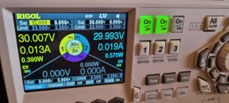
Got all my boards stuff (I love the smell of solder in the morning) and have been trying to test the IPS boards according to the directions in the Build Guide. Have a 2x30V bench power supply with the shunt between the 2 sections going to G1/G2. I have connected ND- to PD+ to NFB. Attached the neg of the VMM to the ground shunt between the two sections.
At 30V per side, the beast draws 0.02A (good!). The measurement NFB to ground gives about -180 mV. Adjusting R25 budges this reading for a few seconds then it returns to -180 mV. It does not seem like it is going to be possible to zero it out.
Have gone over it for shorts, poor joints, etc and corrected a few things so there is no obvious wiring problem (although it is certainly possible to miss something).
Would the next step be two check the voltages against those listed in Stuart's schematic? Since the schematic feeds each side with ~60V, should I be looking for intra-circuit voltages of about half of what is listed on the schematic?
Regards,
J
I had a quick look at this and it appears that the solution is quite simple.At 30V per side, the beast draws 0.02A (good!). The measurement NFB to ground gives about -180 mV. Adjusting R25 budges this reading for a few seconds then it returns to -180 mV. It does not seem like it is going to be possible to zero it out.
All you need to do is ensure that there is ~5mA flowing through R17.
So if your setup for 64v rails and your testing the IPS with 30V rails you could;
1. Temporarily replace R17 with a 5.1K resistor.
2. Temporarily place a 9.1K resistor in parallel with the existing 12K resistor so the net resistance is ~5.1K
Making these changes should allow you adjust the R25 trimpot to achieve a 0mV DC offset measured at the PD+, ND-, NFB node.
I'll add some notes to the Build Guide on this topic.
Good luck.
Just to confirm if you want to test the IPS at 30V you can add a 9.1k resistor in parallel with R17 under the pcb temporarily.I had a quick look at this and it appears that the solution is quite simple.
All you need to do is ensure that there is ~5mA flowing through R17.
So if your setup for 64v rails and your testing the IPS with 30V rails you could;
1. Temporarily replace R17 with a 5.1K resistor.
2. Temporarily place a 9.1K resistor in parallel with the existing 12K resistor so the net resistance is ~5.1K
Making these changes should allow you adjust the R25 trimpot to achieve a 0mV DC offset measured at the PD+, ND-, NFB node.
I'll add some notes to the Build Guide on this topic.
Good luck.
Attachments
Hi mainframe99,
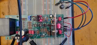
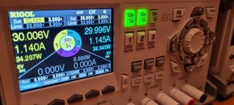
With the 9.1k temporary resistor installed parallel with R17,
I have checked and yes it will work with the whole amplifier connected output stage included.
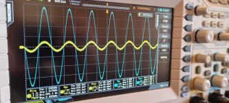
Here is a picture running at full power clipping into 8 Ohms with only 30V dc rails.
The constant current sources can be checked and you can check the bias function and dc offset also.
I hope this is useful for you.
With the 9.1k temporary resistor installed parallel with R17,
I have checked and yes it will work with the whole amplifier connected output stage included.
Here is a picture running at full power clipping into 8 Ohms with only 30V dc rails.
The constant current sources can be checked and you can check the bias function and dc offset also.
I hope this is useful for you.
Attachments


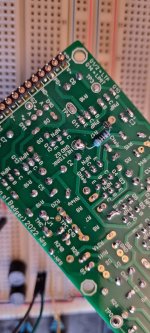
I got these to-220 rectifiers from earlier build. 20A. Are they considered too small for Wolverine (70V)?
Mounting on heatsink is possible.

Mounting on heatsink is possible.
It depends on how much capacitance you want to hang off the other end of them.
I am running 20A inline bridges and they run quite warm.
I usually prefer 35A or 50A bridge rectifiers bolted to the chassis to be honest, for example the KBPC3510 or similar.
Hope this helps
- Dan
I am running 20A inline bridges and they run quite warm.
I usually prefer 35A or 50A bridge rectifiers bolted to the chassis to be honest, for example the KBPC3510 or similar.
Hope this helps
- Dan
Thanks for confirming this @danieljw I'm super appreciative of your support. 🙏Validating what I was able to see in simulation is very helpful and the people here who are building can now have the confidence their build is ok, using this low voltage validation test. I will update the build guide accordingly.With the 9.1k temporary resistor installed parallel with R17,
I have checked and yes it will work with the whole amplifier connected output stage included.
It depends on how much capacitance you want to hang off the other end of them.
I am running 20A inline bridges and they run quite warm.
I usually prefer 35A or 50A bridge rectifiers bolted to the chassis to be honest, for example the KBPC3510 or similar.
Hope this helps
- Dan
I’m currently using 44000uF per rail. No issues to power up.
Wouldn’t 20A at 70VDC equal 1400W or is that to simplify too much?
- Home
- Amplifiers
- Solid State
- DIY Class A/B Amp The "Wolverine" build thread