Mailman came by today!
Thanks to @fireanimal once again, this time for providing me with the much needed Transistor Matcher! All SMD's presoldered at my request... Absolutely amazing 🙂

Thanks to @fireanimal once again, this time for providing me with the much needed Transistor Matcher! All SMD's presoldered at my request... Absolutely amazing 🙂

Interesting. Means not much current going through the bias circuit, and probably the reason it doesn't provide the necessary bias voltage for the output stage. Zero bias also means a lot of audible distortion. My next step would be to test output board separately (see build guide how to do this with two resistors).You may be on to something -- I'm reading 170.8 mV across TP-3 and TP-4. I don't what that means in terms of a failure in the circuit, however.
All parts ordered, including the last part needed for the transistor matcher.... I decided for one packed shipping, so with backorders in the basket it'll be late December or January before the fun can begin.
For the diff-section transistors at the input stage I ordered BC327TA/BC337TA
Regards
For the diff-section transistors at the input stage I ordered BC327TA/BC337TA
Regards
Last edited:
What parts are on backorder? Everything should be in stock, no? BC327-40 and BC337-40 work great, is that what you ordered?
Yes the 40-type... It's because I've ordered the On-Semi branded BC327/337 where the 327's is on backorder. Also the caps for the matcher it out of stock.
Folks:
One other question: R109 on my two Wolverine EF3-3 (v3.9) GB1 boards is 200R. Should it be replaced with a 500R pot (as seems to be the case per the latest Build Guide)?
Regards.
One other question: R109 on my two Wolverine EF3-3 (v3.9) GB1 boards is 200R. Should it be replaced with a 500R pot (as seems to be the case per the latest Build Guide)?
Regards.
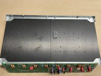
@fireanimal I see you did this EF3-4 build of my interest after I've searched the thread regarding MT-200 output transistors.
Did Modushop do the drilling on these heatsinks?
I only aske as this might do my future order of a 400mm/4U chassis much easier if they already have the drillfile.
Thanks
Did Modushop do the drilling on these heatsinks?
I only aske as this might do my future order of a 400mm/4U chassis much easier if they already have the drillfile.
Thanks
Attachments
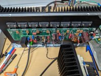
I drilled and tapped those, but modushop has the drill pattern for the EF3-4 and MT-200 outputs.
https://modushop.biz/site/index.php...duct_id=811&search=wolverine&description=true
Under the price is a drop box to select what outputs you want it drilled for.
https://modushop.biz/site/index.php...duct_id=811&search=wolverine&description=true
Under the price is a drop box to select what outputs you want it drilled for.
Thats the Q103/104 change I mentioned you do earlier. There are a whole raft of changes associated with that change, you cannot just swap R109. See the latest BOM and this post here:Folks:
One other question: R109 on my two Wolverine EF3-3 (v3.9) GB1 boards is 200R. Should it be replaced with a 500R pot (as seems to be the case per the latest Build Guide)?
Regards.
https://www.diyaudio.com/community/...he-wolverine-build-thread.385920/post-7360185
I’m a bit confused by the build guide and chapter 21.3. Heatsink hole location.
I have a 5U, 400mm and TO-264.
In the build guide it looks like I’m off by 5mm to use the UMS standard hole.
Why would I not use those 8 pre-drilled holes?
Thanks
I have a 5U, 400mm and TO-264.
In the build guide it looks like I’m off by 5mm to use the UMS standard hole.
Why would I not use those 8 pre-drilled holes?
Thanks
Before I purchase larger heatsinks I want to make sure they are big enough...@90scaraudio
With all due respect to your construction, I would like to draw your attention to the size of the heatsink, which I see is small if I judge from my own heatsink. you will have quiescent current stabilization issues at 44mv it will try lower and lower to stabilize it . You must put fan coolers.
For each channel (EF3-3) I think I can use two of these per board. They are 184.9mm wide, so that would total 369.8 mm. Hight is 127mm and it has a 7.62mm thick plate with 25.4mm fins. I would of course get four of these, two for each channel.
Does it look ok?
https://www.heatsinkusa.com/7-280-wide-extruded-aluminum-heatsink/#gallery-2
You could if desperate, but the transistor legs would be bent past 90 degrees/excessively/awkwardly, especially if you use 8mm heatsink standoffs. The TO-264 package is taller than TO-3 making the bend point for the legs lower down, and the holes on the UMS heatsink are designed for TO-3 transistors. If using TO-264 it is strongly recommended to tap new holes higher up so the TO-264 legs are bent at 90 degrees into the EF3 PCB.I’m a bit confused by the build guide and chapter 21.3. Heatsink hole location.
I have a 5U, 400mm and TO-264.
In the build guide it looks like I’m off by 5mm to use the UMS standard hole.
Why would I not use those 8 pre-drilled holes?
Thanks
Thanks for reply @mainframe99
Perhaps my drilling isn’t UMS?
No other holes can be used beside output transistors!
Perhaps my drilling isn’t UMS?
No other holes can be used beside output transistors!
Attachments

have you got any TO-3's to do a sanity check? find the holes that work for the PCB, then go from there. I believe the UMS was meant for TO-3's and not TO-264s. So the holes should all line up with the PCB and TO-3's, however for the EF3-4 an additional 2x PCB mounting holes need to be drilled anyway, and you will need to drill and tap driver and Q103 holes also, unless you opt for drivers on standalone heatsink.
Or yes as you say, your heatsink hole pattern is for something different entirely, may take more experience members to chime in here.
Or yes as you say, your heatsink hole pattern is for something different entirely, may take more experience members to chime in here.
Last edited:
Someone correct me if I'm wrong but this is my understanding of it for @deerhunt 's case (AS opted for TO-264 outputs), I don't have a 'UMS' heatsink here though.
Should be no need to drill/tap anything if you opt for TO-3 outputs and ignore the two outer-most PCB support holes, AND use separate driver heatsinks, although your PCB will be flimsy until the outputs are soldered in place.

Should be no need to drill/tap anything if you opt for TO-3 outputs and ignore the two outer-most PCB support holes, AND use separate driver heatsinks, although your PCB will be flimsy until the outputs are soldered in place.
That’s not ums for sure.Thanks for reply @mainframe99
Perhaps my drilling isn’t UMS?
No other holes can be used beside output transistors!
- Home
- Amplifiers
- Solid State
- DIY Class A/B Amp The "Wolverine" build thread