
Just a last one; UES 220uf with a diameter 12.5mm will limit the voltage rating to 35V... Is this to tight of a tolerance, or should I stick to the recommended 220's in the BOM?
EDIT; all recommendations is 63V except one 50V... Therefore I chose to add ECE-A1HN221UB (50V) to the basket due to the 2000hours life, so skip my 35V question 🙂
EDIT; all recommendations is 63V except one 50V... Therefore I chose to add ECE-A1HN221UB (50V) to the basket due to the 2000hours life, so skip my 35V question 🙂
Last edited:
Its hard to say at this point.
It might be a good idea to try and validate a few of the other DC voltages shown on the schematic. The voltages shown are what you should measure approximately when the amplifier has the input shorted. If your not getting anything at those test points you tried, try at the nets I selected.
You can also print out the schematic and measure voltages and then write the voltage you measure on the schematic. You can then post your values to help with the diagnosis.
Good luck 🤞
Stuart & Co.:
Sorry for the belated response; we were inundated with family over the past few days which made diving into the amplifier impossible. Now that our family has left, I have time to spend on my amplifier problem.
Here are the basics, with the input shorted and nothing on the output:
Rail voltages: +/- 48 VDC
TP101-TP102: 0.0 mV
TP1-TP2: 5.02 VDC
TP100-TP104: 0.1 mV DC
TP100-TP104: 0.0 mV AC
R109 is a 200R pot and is working perfectly, contrary to my earlier assumption. However, the reading across TP101 and TP102 stays at 0.0 mVDC regardless of how R109 is adjusted.
I took a few readings (and would be happy to take far more) with DMM- at PSU Gnd:
D105A (cathode side): 0.383 VDC
D106A (anode side): 0.427 VDC
R110: 0.153 VDC (same reading on both ends)
C110: 48 VDC (on the rail side)
C110: 0.382 VDC (on the other side)
C111: -48 VDC (on the rail side)
C111: -0.423 VDC (on the other side)
I don't know which other readings would be relevant in diagnosing the issue with this amplifier.
All advice / questions are appreciated!
Regards,
Scott
Attachments
Not to be rude, If TP3-TP4 doesn't give some clues, and all components tests good in diodemode ect (no power applied!), then you really should invest some time to reflow some of those solderjoints.. It's a 2-layer PCB, and lack of solder could easily be your bad connection.
Happy hunting 🙂
//best regards
Happy hunting 🙂
//best regards
Lower voltage are fine on the GB2 boards there was protection diodes added
10kohm input, C9: I've added a Nichicon UES 100uf/50V to the basket at Mouser...
Alternative is 220uf also mentioned in the BOM as an option, would this perform better?
Thanks
after checking VAS CSS TP3 TP4- @SRMcGee - a clue here perhaps, after all you mentioned heavy distortion, could C9 be bad, as GB1 boards?
Not to be rude, If TP3-TP4 doesn't give some clues, and all components tests good in diodemode ect (no power applied!), then you really should invest some time to reflow some of those solderjoints.. It's a 2-layer PCB, and lack of solder could easily be your bad connection.
Happy hunting 🙂
//best regards
hcpower:
You're not being rude at all. I neglected to mention that all of the solder joints have been reheated and look fine.
kokkie:
I'll check CCS2 across TP3 and TP4 either later on tonight or first thing tomorrow and report back.
mainframe99:
Just to be clear, the amplifier was working just fine for almost exactly one year before the right channel started sounding faint and garbled. Is it likely a capacitor would just give up the ghost in that short a timeframe? If C9 might be the culprit I'll certainly be happy to swap it out for something else, but wonder whether other testing first might be smart? That said, I do have some Nichicon UVZ 100uF 100V caps on hand (unless something else is strongly recommended)....
Thanks everyone!
Regards,
Scott
Last edited:
Scott, it's definitely above my skill level, I'm just trying to help brainstorm. It looks like in GB2 they added protection diodes for C9, so wiser heads here may be able to comment on if this is a possible failure point if a suboptimal part is installed there. It is the feedback DC decoupling cap no? So, directly responsible for distortion reduction? I most likely am wrong, I'm very beginner with amplifier circuits.
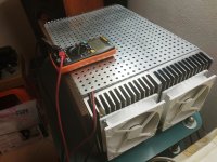
OK, Question....@90scaraudio
With all due respect to your construction, I would like to draw your attention to the size of the heatsink, which I see is small if I judge from my own heatsink. you will have quiescent current stabilization issues at 44mv it will try lower and lower to stabilize it . You must put fan coolers.
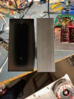
I'm going to compare a heatsink from an amp that was built in the early 80's and I've had it since 84.
Here are the spec's...
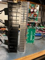
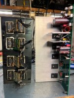
Here is the heatsink as a comparison to what I'm going to use for the Wolverine,
Notice the M2 put the equivalent of 16 semi's, (8 per channel)
The rail's are at 90v's.
Yes, it does have a fan but it's never turned on... Curious, I checked it with my hot are gun and indeed it does work.
So can someone explain to me why the heatsinks I'm using, BTW, one of the new Heatsinks is heavier than the M2 heatsink and It's only cooling halve the semi's, so why am I being told they are too small???
Oh, I did reflow a couple low-spots on the boards.... Thanks for that... Sucks getting old...
Scott
Attachments

dang - and safe to say most of that was coming out of the main heatsinks too. Bet the fans came on after a couple minutes if you dropped rated loads into a load bank continuous.
My EF3-3 at idle is taking about 90-100W from the wall, haven't done a full power check yet though.
I did the DRM Audio Upgrade on it just because some of the parts for this old amp were becoming hard to find.
Some good information from JJS member.Nikos, you could perhaps help 90's caraudio (and me), do you know of a decent online source where one could calculate the minimum required heatsinking? I assume the BOM listed size / DIYaudio chassis heatsinks at 300x40x160mm must be sufficient for a 3 pair 70V rail build i.e. 240W 8R/ 430W 4R, as there is no mention otherwise, so how does one calculate the required heatsinking should they be doing a lower voltage, lower power build?
Is it as simple as percentages, i.e. if rails are 54vdc and your power overall is 40ish percent less, can one get away with a heatsink that is 40ish percent smaller?
Sorry, this has probably been discussed ad nauseum amongst more expert members here.
https://www.diyaudio.com/community/...son-of-badger-suggestions.369758/post-7026095
https://www.diyaudio.com/community/...son-of-badger-suggestions.369758/post-7026131
My dimensions heatsink 40x 155 x 280 mm ~ 57V with an ambient temperature of about 30-32 in the summer the temperature on my heatsink reaches about 42-45 C without continuous loud music, with the quiescent current down at 30 mv.....now with the coolers fan ready steady always 38 C and quiescent current between 42-45mv with continuous loud music. And the flow of the fans should work at about 20% and keep this temperature constant at 38 C in a calm state the amplifier.🙂🙂🙂🙂🙂
Attachments
Last edited:
I just realized that this amps bias setting is set to 100ma!! Wow, no wonder the need for large heat sink!
Now I really have to rethink this... 44mv divided by .44 = 100ma (0.1amps)
Scott
Now I really have to rethink this... 44mv divided by .44 = 100ma (0.1amps)
Scott
Scott, it's definitely above my skill level, I'm just trying to help brainstorm. It looks like in GB2 they added protection diodes for C9, so wiser heads here may be able to comment on if this is a possible failure point if a suboptimal part is installed there. It is the feedback DC decoupling cap no? So, directly responsible for distortion reduction? I most likely am wrong, I'm very beginner with amplifier circuits.
mainframe99:
You may be on to something -- I'm reading 170.8 mV across TP-3 and TP-4. I don't what that means in terms of a failure in the circuit, however.
Regards.
Many of the OEM's , to use cheaper heatsinks - bias at far lower total dissipation. Input stage topology will allow some to have great fidelityI just realized that this amps bias setting is set to 100ma!! Wow, no wonder the need for large heat sink!
Now I really have to rethink this... 44mv divided by .44 = 100ma (0.1amps)
Scott
at even 30-40mA per device. At 200+ V/uS (CFA) , feedback can even "correct" obscene crossover glitches (under-biased EF3).
Different output types (Sanken ,toshiba... ON) have different "sweet spots". Most likely it is architecture , ring emitter/planar....
OS
- Home
- Amplifiers
- Solid State
- DIY Class A/B Amp The "Wolverine" build thread