Wolverine is better "amp porn" than all but the most extreme of overpriced audiophile BS I've seen. Fireanimal's MT-200 monster is by far the best
DIYA amp so far.... And has the specs to match. I had a 3 pair MT-200 sanken drive a 4 ohm 350 watt sub to Xmax easy.
DIYA amp so far.... And has the specs to match. I had a 3 pair MT-200 sanken drive a 4 ohm 350 watt sub to Xmax easy.
Just a hint to those who order at Mouser or Digikey or similar: It will save a lot of time if you use the "customer reference" field for the names given in the BOM, e.g. R17, when ordering.The only regret is not building with vishay as it is much easier to read numbers than stripes.

I've had my trouble with some OLEDs and their SPI interfaces introducing lots of noise during communication. Especially in combination with Arduinos.You could do full color OLED (spectrum) or full RGB bargraph VU/power with a single AT328 7$ CPU and W2812b led's.
Photo 2 is what is on my wall - .01 to 60W or -70db to +6db. I could scale it to any amp/input. Along with the metering , any power level
could become a digital output to mute the amp (or reset it). ESP32 wifi , one can even adjust amp bias and volume with a phone. yeah !!
Thanks for the compliment! It is a beast, I just need to get another pair built and into a couple chassis now...well when I find the time lol.Wolverine is better "amp porn" than all but the most extreme of overpriced audiophile BS I've seen. Fireanimal's MT-200 monster is by far the best
DIYA amp so far.... And has the specs to match. I had a 3 pair MT-200 sanken drive a 4 ohm 350 watt sub to Xmax easy.
ever try shielded twisted pairs ? "some oled's" = some china junk ?? I use a resistor + a shielded data for 800khz pwm to my leds. lots of decoupling in a long run of power + data.I've had my trouble with some OLEDs and their SPI interfaces introducing lots of noise during communication. Especially in combination with Arduinos.
ahh ... https://www.nxp.com/docs/en/engineering-bulletin/EB393.pdf R in series + 1nF decoupling right on the data lines...
Among others, I used a cheap SSD1331, like this one https://funduinoshop.com/elektronische-module/displays/oled/ssd1331-oled-0.95-96x64-farbdisplay-spi
I needed some coupling between DGND and AGND, as I wanted to control digipots. Maybe the coupling was too direct and induced lots of noise onto AGND 😡
I needed some coupling between DGND and AGND, as I wanted to control digipots. Maybe the coupling was too direct and induced lots of noise onto AGND 😡

@voxxonline I don't know. The older I get, the happier I am for the pretty colored stripes.🙂 It saves me from having to sort everything under the microscope.The only regret is not building with vishay as it is much easier to read numbers than stripes.
Hi Guy's
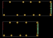
For those who would like to design there own IPS addition to the Wolverine family.
I have added the Sprint Layout IPS templates file to the 1st post of this thread.
One template will suit both the EF3-3 & EF3-4 precision output boards and one template will only suit the EF3-4 precision output board.
The mounting holes shown are all the possible holes that will line up with the EF3-3 & EF3-4 precision output board below.
Feel free to delete any of the mounting holes to achieve your desired IPS layout, but please ensure you leave enough to support you new IPS board.
Good luck.
Attachments
If I find the time I will try attaching some of mine Slewmaster IPS with flying wires to this Wolverine output.😉
Last edited:
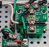
I notice that the traces on the ground lift boards above are large, in case of a mains fault. Unfortunately other boards I have seen, use very thin traces.
@Harry3
Excellent point. In fact, in all my builds, I use the thickest wire (i.e. lowest gauge) going from my chassis ground to the IEC ground, precisely for this reason.
Chassis ground is fundamentally the most important safety measure (other than the mains fuse) and there should be little to no impediment in case of fault.
I love Stuart‘s boards!
Best,
Anand.
I have some shielded speaker cable I want to use to connect the wolverine output to the binding post. Should I connect the shield at the binding post to the chassis and open at the wolverine side? Like you would do with the RCA inputs.
Or is it better to not connect the shield to reduce capacitance to chassis.
Thanks for your help.
Or is it better to not connect the shield to reduce capacitance to chassis.
Thanks for your help.
Last edited:
fireanimal:
Can you show me your measuring device?
Is the measurement of the test oscillator available?
Can you show me your measuring device?
Is the measurement of the test oscillator available?
Do not reinvent the wheel, your asking for trouble.I have some shielded speaker cable I want to use to connect the wolverine output to the binding post. Should I connect the shield at the binding post to the chassis and open at the wolverine side? Like you would do with the RCA inputs.
Or is it better to not connect the shield to reduce capacitance to chassis.
Thanks for your help.
Use good quality thick, stranded copper wire for speaker output.
- Home
- Amplifiers
- Solid State
- DIY Class A/B Amp The "Wolverine" build thread