@Studley , though I have not used them and haven't seen a lot on the forum about them, I have no doubt the soft start and speaker protection kits from ampslab will work as another option. https://www.ampslab.com/products.htm
The store's boards may be a better option, and you could source parts in the UK.
The store's boards may be a better option, and you could source parts in the UK.
I feel quite conflicted about it myself. On the one hand I think, why pay more when there are cheaper options but on the other I think about how much an amp like the Wolverine would cost if produced by a “high end” brand and therefore I shouldn’t balk at spending £150+ on a top quality soft start module!@Studley
Acknowledged. Valid point.
When I walked into the world of DIYAudio, I have most definitely looked the ’other way’ with regards to price on most things! But that’s not a perspective that all can share, and I empathize with that!
Best,
Anand.
@Studley
Not to belabor the point but my greatest concern isn’t with a soft start. That’s of course a nicety and preferred for all toroid sizes that are greater than or equal to 400VA. There are plentiful options out there for various budgets. Christiansen has published on his website the tremendous currents drawn when you first turn the amplifier on, it’s a big stress on the power switch.
My greatest concern is with the recommendations for the speaker protection modules.
As much as fireanimal has shown us that the various input cap varieties aren’t impediments to the overall THD of this design, we also need to look at the tail end of things. The speaker protection module is on the output of this amplifier. It must not be an impediment given the tremendously low overall THD of the design.
The Modulus 686 is also very low in THD. And it has been tested with the Guardian 686 (not 86 since it’s a balanced output). The Guardian module isn’t an impediment to that design at various output powers. That’s a fact that has been published and proven.
Why would I choose anything less for the Wolverine amp? Tremendous efforts have been placed by numerous diyAudio members spanning the entire globe in making this one of the lowest distortion discrete designs out there. Why choke it at the end?
I’m not going to get into the ‘sonics of speaker protection modules’ and such. That’s a rabbit hole one cannot climb out of and results in endless circuitous discussions that essentially go no where.
Enough ranting, back to the usual fanfare - sorry about that!
Best,
Anand.
Last edited:

Looks like a future task for me. Assemble a few different speaker protection boards to test. No matter what though guys whoever's speaker protection you go with do NOT get a relay based one please.
I'm running my Wolverines straight to the banna posts and I have been running like this for over 6 months without one issue.
I'm running my Wolverines straight to the banna posts and I have been running like this for over 6 months without one issue.
I'd like to point out that some speaker protection designs "only" offer DC sense on the output with delayed turn on time and fast cut off time.
Other designs also monitor the loss of AC, high temperature, high current etc.
Choose a design that you are happy with.
Other designs also monitor the loss of AC, high temperature, high current etc.
Choose a design that you are happy with.
Speaking on input caps. I've been doing a few more tests. Does anyone think orientation would matter on a bipolar film cap?.... I didn't. l Will have more results in the next couple days.
You are lucky enough to use a SMPS, so I guess you don't get a "pop" when turning on your Wolverine? The main reason for me to get speaker protection modules would be the delay on turn-on to avoid the pop.. What kind of speaker protection modules without relays could solve this problem?I'm running my Wolverines straight to the banna posts and I have been running like this for over 6 months without one issue.
I am weary of asking questions just not to feel stupid over here 🙂 non the less,
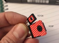
Isolation of transistors. Exposed areas hatched red.
If a fully plastic encapsulated transistor is- no isolation is needed. A small amount of grease and that's all.
Transistor of To3 type with the exposed surface but sufficiently isolated screw area. Just a tape/ pad + a small amount of grease, depending on the insulation used.
If the transistor to TO-126 depicted is used- tape and shoulder washer + grease are needed, due to the small isolation area around the screw.
Correct?
Attachments
I do still get a small pop when I turn them on, but my solution is to never turn them off 😀.You are lucky enough to use a SMPS, so I guess you don't get a "pop" when turning on your Wolverine? The main reason for me to get speaker protection modules would be the delay on turn-on to avoid the pop.. What kind of speaker protection modules without relays could solve this problem?
Solid State is what I was referring too, not mechanical relays.
Examples
https://hifisonix.com/projects/hifisonix-speaker-protection-board/
https://www.etsy.com/ca/listing/932...16741&click_sum=ca3e72b8&ref=shop_home_recs_8
https://neurochrome.com/products/guardian-86
I'm sure there are probably others I am missing.
Only stupid questions are the ones that are never asked.I am weary of asking questions just not to feel stupid over here 🙂 non the less,
Isolation of transistors. Exposed areas hatched red.
If a fully plastic encapsulated transistor is- no isolation is needed. A small amount of grease and that's all.
Transistor of To3 type with the exposed surface but sufficiently isolated screw area. Just a tape/ pad + a small amount of grease, depending on the insulation used.
If the transistor to TO-126 depicted is used- tape and shoulder washer + grease are needed, due to the small isolation area around the screw.
Correct?
Fully encapsulated - Grease*
TO-126 Metal Back - Isolation Pad and Grease*, No shoulder washer required, I only use those on metal tab TO-220
All Output Packages - Isolation Pad and Grease*
*This would depend on the type of Isolation used. Kapton tape, or mica I would put a little bit on spread evenly, but keratherm or the likes does not.
For TO-126 I used these https://www.mouser.ca/ProductDetail/Wakefield-Vette/173-7-220P?qs=VVKQmw408U%2BV03GlhN45fQ== and then cut to the correct size.
Here are 2 comparisons Mundorf and Solen Silver Sound. All I did was flip the cap with either label pointing into the IPS or label pointing out from the IPS.
I bought the Silver sound to see if a $50 cap would be any better then the $15-20 ones I tried before, but when I received it, I noticed 1 leg was marked with black sharpie, and thats what led me down this path of testing.
As you can see there is a large difference depending on how the cap is installed, but still in neither of these cases do the caps reduce distortion lower then the BOM cap.


Here are the Box type caps that I tested, and orientation does not matter with these, I tested and there was no change.

And overlayed results, highly magnified with linear scale to be able to start to separate them. Basically all fall within measurement error.

Long story short, If you do use an audiophile cap, then please make sure it is oriented correctly for best performance! Or save 50 bucks and just buy the Vishay 😁
I bought the Silver sound to see if a $50 cap would be any better then the $15-20 ones I tried before, but when I received it, I noticed 1 leg was marked with black sharpie, and thats what led me down this path of testing.
As you can see there is a large difference depending on how the cap is installed, but still in neither of these cases do the caps reduce distortion lower then the BOM cap.
Here are the Box type caps that I tested, and orientation does not matter with these, I tested and there was no change.
And overlayed results, highly magnified with linear scale to be able to start to separate them. Basically all fall within measurement error.
Long story short, If you do use an audiophile cap, then please make sure it is oriented correctly for best performance! Or save 50 bucks and just buy the Vishay 😁
@fireanimal
So what you are saying (by measurement criteria) is that the orientation of the outer foil of some of these caps makes a measurement difference. Now, do you happen to know where the outerfoil of the caps should be connected on the schematic and/or the IPS pcb so builders can Implement the orientation properly of said cap?
Thanks for all your hard work…really!!
Best,
Anand.
Technically speaking you want the outer foil to always go to the lower impedance part of the circuit. Here's a good video on the subject. It's a little wordy but also gives a quick method to find it and little circuit you can build to find the outer foil.
Only the solen was marked for the outer foil and this gave the lowest distortion measurement installed this way. But it seems like that is opposite of what is recommended. I need to measure the other caps to see which lead is on the outer foil to confirm, and check this one incase it was marked incorrectly.

The snake oil capacitors have a certain entertainment value. Those who want to be scammed must be given the opportunity. Ter leering ende vermaeck (For learning and entertainment).
However, I be interested in a comparison between various types of capacitors from a single respectable manufacturer.

However, I be interested in a comparison between various types of capacitors from a single respectable manufacturer.
- Home
- Amplifiers
- Solid State
- DIY Class A/B Amp The "Wolverine" build thread