Allow me to stray from topic if but for a second. According to my old friend George Orwell, the Hi-fi police shall impose class D or higher. All I want is to die within a world that I know. Carry on-this is merely an old guy's lament. The rate of change has outrun me.

Love a good LPS in a Class A or A/B amp.
That being said, SMPS have come a long way over the past decade or so. Even just shifting noise to supersonic regions is beneficial compared to "fighting" 60/50Hz harmonics.
That being said, SMPS have come a long way over the past decade or so. Even just shifting noise to supersonic regions is beneficial compared to "fighting" 60/50Hz harmonics.
I am using them in multiple applications, low current for dacs and preamps, mid current for SBC powered streaming, and large amperage for amps. Side by side comparison to linear power SMPS supplies the are less sensitive to input voltage fluctuation and reject noice better, and run cooler. The down side for good quality ones they cost more at this point and are not diy buildable ( practically), and I even have several class d amps I am impressed with. I have even gotten over thinking discreet circuits are always better than opamps, and have embraced soldering smt. At 70 old dogs can learn new tricks.
Bill
Bill
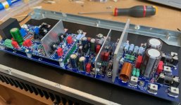
I have one channel up and running. I finally decided to put Q104 on the heatsink. When mounted on top of Q113 the bias dipped below 20mV after a high power episode. With Q104 on the heatsink the bias seems more stable, but I might be wrong. I also used a TTC004 (fully isolated package) instead of the recommended MJE340. Everything seems to work fine. The measured THD at 1kHz, 25W and 4ohm is below the distortion of my test setup.
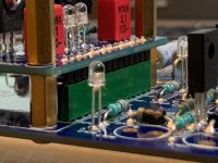
By the way, I used an alternative for the male and female SIP1 connector that can be used with 10mm standoffs and which can easily be sourced from other suppliers as well. The female base is the TE Connectivity 1-215297-4 (for example Farnell Ref. 3398239) which has a height of 7mm and accepts 0.63mm square pins.The male pin connector is the Samtec TSW-114-07-G-S (for example Farnell Ref. 2856753) which has a base of 2.54mm and square pins of 5.84mm length. Both are gold plated and readily available from other suppliers. As you can see in the image they are a perfect match with 10mm standoffs.
By the way, I used an alternative for the male and female SIP1 connector that can be used with 10mm standoffs and which can easily be sourced from other suppliers as well. The female base is the TE Connectivity 1-215297-4 (for example Farnell Ref. 3398239) which has a height of 7mm and accepts 0.63mm square pins.The male pin connector is the Samtec TSW-114-07-G-S (for example Farnell Ref. 2856753) which has a base of 2.54mm and square pins of 5.84mm length. Both are gold plated and readily available from other suppliers. As you can see in the image they are a perfect match with 10mm standoffs.
Attachments

Not sure, you may have missed the 10mm option in the BOM;
Also I would NOT be switching the MJE340 for the TTC, RCC is fined tuned for the MJE340, and you could introduce a lot of error in the bias spreader.
| Alternatives for 10mm standoffs ====> | 14 Position Pin Header Gold (Male SIL) for 10mm standoff | Round 575-8001001410001000 | ||
| 14 Position Female Gold socket for 10mm standoff | Round 437-8018301410001101 |
Also I would NOT be switching the MJE340 for the TTC, RCC is fined tuned for the MJE340, and you could introduce a lot of error in the bias spreader.
I have a 600VA 4x38Vac transformer which gives me +/-55V. That is why all my caps are 63V.
Hello Gents
Earthing question. I'm using the groundloop breaker circuit of Rod Elliot. My toroidal transformers have there own ground wire each. Do I connect them directly to the chassis or to the groundloop breaker and then to the chassis like all the others?
thx in advance

.jpeg")
Earthing question. I'm using the groundloop breaker circuit of Rod Elliot. My toroidal transformers have there own ground wire each. Do I connect them directly to the chassis or to the groundloop breaker and then to the chassis like all the others?
thx in advance
The wires from the transformers are not grounds, they are screen wires, and should be directly wired to chassis ground.
THD1k 0.0012% and SNR 80dB is not good. Is it a measurement problem or something else ?The measured THD at 1kHz, 25W and 4ohm is below the distortion of my test setup.
Absolutely a measurement problem. Forgive me, I should have mentioned that this is not an accurate THD measurement of the Wolverine, but only a test to see if the amplifier works as it should. After building several tube and Pass amps, I had not yet achieved such a low THD measurement at this power level before...
For the anecdote, I can even tell you that I completely fried those beautiful resistors in the Zobel network in a moment of inattention when I connected my test equipment without a proper signal ground point. In a split second, amp went into oscillation and my oscilloscope went wild, mains fuse blew and that distinctive burning smell that all electronics DIYers know all too well. No harm done. I replaced the resistors, attached a proper ground and everything worked fine. Moral of the story : buy some extra resistors in advance and don't trust my measurements.
I am acquiring parts for a Wolverine build. I was asked what input impedance I preferred. The two options are the default at 10 k and 22k. My understanding is that the 22k option would better accommodate a tube front end. My question is thus-is there a way to integrate both into a build? My very basic thinking is that I could add another set of input jacks and replicate the parts values for an alternate input impedance and wire it into the board at the same junction, perhaps shorting the other input at the same time. It seems to me this would be a lot easier up front rather than changing the values on the boards later should one want to experiment with a tube front end.
Please see Post #1 of this thread for measurements taken by me please.THD1k 0.0012% and SNR 80dB is not good. Is it a measurement problem or something else ?
https://www.diyaudio.com/community/...he-wolverine-build-thread.385920/post-7014086
I did specify 10k and plan to initially go ss. I just have about 5000 tubes around here and like to play with them sometimes. I must admit I kinda' like the sound-like butta'. I am just curious as to whether multiple input impedances can be easily implemented.
@Toolermike
I agree with fireanimal.
The Wolverine was designed with a level of fidelity in mind. I would argue that with lower noise floors maximizes ones ability to listen to the AC music signal and to that end, the 10K input impedance is a better choice.
I’m not sure what you mean by a tube ‘front end’ but I am assuming a tube preamp or a tube output stage on the phono side or a tube output stage on the dac side. That’s fine, but I would try very hard to make sure that the output impedance of said stage is less than 1K ohms (at the worst). And this limit should be there from 20Hz to 20khz. Many designs will report a low output impedance but when measured you will find that it is there at only certain frequencies, not throughout the audio spectrum (20Hz to 20khz).
This is DIY and you can do as you please of course.
Best,
Anand.
- Home
- Amplifiers
- Solid State
- DIY Class A/B Amp The "Wolverine" build thread