Peppennino is Viking Talian, Andy is Talian Viking
go figure
I can't

go figure
I can't


Pulcino also in stock 🙂dama are for sissies 😀
Hello rewind (post1115),
daisy-chaining two of the 6-24AXO is exactly what I am doing. Only different crossover-frequencies (for my speakers demands).
AXO 1: crossover from sub to 2-way (mid-highs) at 80 Hz
AXO 2: crossover from midbass to tweeter at 2500 Hz. Gets the signal from AXO 1 high-pass above 80 Hz
As you described it - it is a bandpass (in my case 80 - 2500 Hz).
I only have one PSU for each AXO.
Cheers
Dirk🙂
Attachments
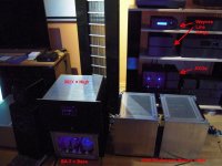
rewind, I forgot to say: nice horns!
Your ears shall be blown through in a satisfactory, mindblowing listening scenario... 🎼🎸
Have fun!
Dirk
Your ears shall be blown through in a satisfactory, mindblowing listening scenario... 🎼🎸
Have fun!
Dirk
Very nice setup.Hello rewind (post1115),
daisy-chaining two of the 6-24AXO is exactly what I am doing. Only different crossover-frequencies (for my speakers demands).
AXO 1: crossover from sub to 2-way (mid-highs) at 80 Hz
AXO 2: crossover from midbass to tweeter at 2500 Hz. Gets the signal from AXO 1 high-pass above 80 Hz
As you described it - it is a bandpass (in my case 80 - 2500 Hz).
I only have one PSU for each AXO.
Cheers
Dirk🙂
If using two PSUs, why not use AXO 2 for both the highpass at 80Hz and the Lowpass at 2500Hz. Highpass going to the input of the lowpass. Then the midrange channels uses only one PSU and not two PSUs. Not sure if it will make a difference.
AXO1 would be used for below 80Hz and above 2500Hz. Don't mix them up!
Or better yet, dual mono! For maximum channel separation. Need to check this out if it is possible.
Last edited:
I long ago received my DIY Bi-amp 6-24 board, Jfets and bias resistors. I recently retired so have time to order parts and stuff away.
My first real world use will be on a mini-monitor with 5 inch midbass and planar or ribbon tweeter. Target X-over is 2,500 hz.
My question: Will the 6-24 with "stock version" 10K resistors on board be able to deliver a good 24db L-R 2,500 hz crossover, or should I just go with values derived from the Mike Rothacher spreadsheet? Can anyone speak from experience?
Hello dtaylo3,
you can read the discussion about a possible 6-24 AXO-build with a crossover-frequency at 2000 Hz
in this thread starting at post #982.
Can be easily adjusted to your needs... 2500 Hz crossover frequency
Cheers
Dirk 😉
you can read the discussion about a possible 6-24 AXO-build with a crossover-frequency at 2000 Hz
in this thread starting at post #982.
Can be easily adjusted to your needs... 2500 Hz crossover frequency
Cheers
Dirk 😉
How incredibly impractical. 😶Adjust your trimpots before you solder them in. It is difficult / impossible to do this later.
Cheers
Dirk 🙂
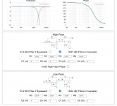
This is what I got. Everything is the same as the 1000Hz example in the article, except I used 4nF and 2nF.I long ago received my DIY Bi-amp 6-24 board, Jfets and bias resistors. I recently retired so have time to order parts and stuff away.
My first real world use will be on a mini-monitor with 5 inch midbass and planar or ribbon tweeter. Target X-over is 2,500 hz.
My question: Will the 6-24 with "stock version" 10K resistors on board be able to deliver a good 24db L-R 2,500 hz crossover, or should I just go with values derived from the Mike Rothacher spreadsheet? Can anyone speak from experience?
I still don't know if this is a 24dB L-R slope.
Attachments
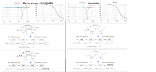
I don't know what slope is in the calculator initially, but maybe this is more a 24LR @ 2500Hz:
Attachments
Last edited:
Back to LSK170 upgrade of Q1:
I measured my J113 and LSK170 JFETS included in the kit. With a new +9 volt battery connected to Drain, and "Gate + Source" connected to a 100ohm resistor. These are my results when I measured across the resistor:
From Kit: J113 measured very nice between 30-31.5mA with 100 ohm included BIAS resistor. "NP, get a hobby." 😛
My sixteen LSK170 [mA]: 27.4, 26.5, 25.8, 24.8, 24.6, 18.0, 17.7, 15.85, 9.72 9.26, 9.22, 9.20, 8.45, 7.90, 7.74, 7.71, 7.57, 7.18, 6.8, 6.42, 6.21, 5.81, 5.78, 5.69.
Now add Ohm's law and voilà!
Not sure what to do now. Do I place all the J113 and start the circuit, and measure the mA over a BIAS resistor (which of them?), then calculate R=V/I, since I now know both mA and Voltage (do I)?
Last edited:
I guessing the LSK170 with IDSS: 27.4, 26.5, 25.8, 24.8, 24.6 mA, can replace the 30-31.5mA J113 using the included 100 ohm resistor? No dramatic change.
But I have two boards, and need to replace four more J113 with LSK170.
But I have two boards, and need to replace four more J113 with LSK170.
Could you clarify/speak to me as if I am a 5 year old (no disrespect to 5 year olds)?Now you measure your J113 and adjust the bias-resistor of the J113 to get the desired mA-value
running through your active upper JFet.
Cheers
Dirk 😉
I remember from my B1 and F5 build that an 8mA LSK170 was more desirable and they all sold out for years. Is this also the case with Q1 in the 6-24 crossover buffer?if arranged as that, you must keep source resistors in upper portion of buffer
observe, you'll see that buffer is practically biased ( Iq set) with source resistor in lower JFet ( CCS), while role of upper source resistor is to establish so-so same DC levels at buffer input ( upper JFet gate) and its output
yeah - if having matched JFets in range of 9mA, just keep all source resistors of same value
whatever you have in range of 4R7 to 10R
So I will just solder a wire in place of the bias resistor closest to 1K resistor in the input buffer, and put a LSK170 in place of the J113 at W1 at the input buffer. Which Idss should the LSK170 at Q1 in the input buffer have? Pick any value, I have 4-27mA.Q2 is just a constant current source and the bias is set by the Source resistor to ground. The Source resistor of Q1 is not actually necessary and you can replace it with a short. If you want to replace Q1 with a 2sk170, then you can do that and leave Q2 as a J113, but set it's bias resistor so that Q2 runs approximately at the Idss of Q1 or a bit less. Remember that 2sk170 has a different pinout.
This I don’t understand:
«and leave Q2 as a J113, but set it's bias resistor so that Q2 runs approximately at the Idss of Q1 or a bit less.» - NP
Should I take the 30-31.5mA J113 and LSK170JFETs and use my JFET test rig?:
+9V battery to Drain
-9V battery to 100ohm resistor
read Idss on both wires coming out of the resistor.
And then change the 100ohm resistor in the test rig to 150ohm, 200ohm, etc, until it matches the Idss of what I measured the LSK170 to be with a 9 volt and a 100ohm resistor yesterday? And then use this resistor, maybe 200ohm, in the 6-24 crossover as the BIAS resistor for the J113 in Q2?
Last edited:
- Home
- Amplifiers
- Pass Labs
- DIY biamp 6-24 crossover