I’ve just found out about these crossovers and they look great. Anyone know roughly when they’ll be back in stock?
Cheers!
Cheers!
You can use smaller as well - 1000 uf was simply a commonly available value.This is one possibilty to use bigger caps in the filterstage...
Cheers
Dirk
Thanks Dirk. Could you say if these would be better than the Bourns pots ? And perhaps if you can suggest something better still?
| Digi-Key Part Number | 693-M64P503KB40-ND |
Hello RolandPSP,
I have used VISHAY / SPECTROL - sfernice trimmers in many of my builts. Nice parts.
Cheers
Dirk
I have used VISHAY / SPECTROL - sfernice trimmers in many of my builts. Nice parts.
Cheers
Dirk
But I saw, that they are 90 degrees (adjusting screw to legs). Will be difficult to adjust. Perhaps you can find
some with adjusting screw on top and legs down (like 180 degrees).
Dirk
some with adjusting screw on top and legs down (like 180 degrees).
Dirk
Hello RolandPSP,
one possible trimmer (10 kOhm, 0,5W, 21-turn) for crossover-frequency-adjustment:
https://www.mouser.de/ProductDetail...=sGAEpiMZZMtC25l1F4XBUzGGOykc6TTSuzCSpUPoBf0=
You would have to slightly bend the middle pin to make it fit into the pcb.
If you buy more than 10 pieces - 1.56 Euros per trimmer. In my world here in Germany...
Cheers
Dirk
Oh, fabulous PS relay. Where art tho?I put this together as part of a revised power supply filter for the diy Sony Vfet and similar amps
to go in the diyAudio store and I have a nice pile of them ready to ship.
The full supply filter board will be posted more generally later.

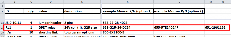
If you're having a hard time finding a relay to fit in your power supply filter PCB, a possible alternative might be to use the Ship Of Theseus power supply filter PCB instead. It was intentionally and deliberately designed to use a relay spec and footprint which is available from multiple different manufacturers. And its coil is intentionally chosen to be 24V rather than 12V, because 24V relays seem to be easier to buy during the *an*em*c induced supply squeeze. Here is a link.
_

_
Attachments

That looks fancy. Since I have two amps it is quite an investment just to get rid of turn off pop.If you're having a hard time finding a relay to fit in your power supply filter PCB, a possible alternative might be to use the Ship Of Theseus power supply filter PCB instead.
Last edited:
JFet is better CCS if there is source resistor
in your boots, I would choose highest Idss from yield, and set Iq with source resistor
your choice
in your boots, I would choose highest Idss from yield, and set Iq with source resistor
your choice
THAT would require further studying. There were attempts at explaining this to me a few pages back, on how to choose source resistor.JFet is better CCS if there is source resistor
in your boots, I would choose highest Idss from yield, and set Iq with source resistor
your choice
quality of CCS is judged by stability and dynamic impedance
stability in domain of time, temperature change and voltage across
dynamic impedance - how it is stable current wise with load impedance variations
so, when I say "better" that's it how it is better
how you're going to set source resistance, that's piece of cake and basic - all you need is to read about JFet basics and apply it
besides myriad of books having exact area covered, I can bet that at least 5 of Papa's articles are covering that too
not to mention JFet Sonic Frontiers by Papa Borbely
As a start, I can say that the highest number I will presumably measure from the 100 pcs of 2SK170BL is around 12mA. If I had chosen 100 pcs of 2SK170V I could have used the same source resistor as Mr Pass included in the kit, and saved myself some months. Oh well.
No, it just means two months of listening to my new 4 inch driver backup system. Great find, btw.oh yeah
some brain engaging and few resistors is suddenly a problem

Hi all,
I am reviving an old project:

I want to try project P71 from Rod Elliot (Linkwitz transform pcb) so I will be using psu with +/- 12v.
As I am testing my EasyEDA skills, I wondered if I could use the +/-12v psu for the 6-24 crossover as well? Is my thinking that V+ in the original schematic can be supplied with +12v, VREF is GND and GND on the jfets (marked below) should be supplied with -12v?

Thanks!
I am reviving an old project:
I want to try project P71 from Rod Elliot (Linkwitz transform pcb) so I will be using psu with +/- 12v.
As I am testing my EasyEDA skills, I wondered if I could use the +/-12v psu for the 6-24 crossover as well? Is my thinking that V+ in the original schematic can be supplied with +12v, VREF is GND and GND on the jfets (marked below) should be supplied with -12v?
Thanks!
That should work fine. Careful matching and/or adjustment of the bias resistors would allow DC coupling as well.
Thanks, I think I will pursue that as well. So I will need to buy a large batch of J113's and unfortunately no one to pay for measuring:

😉
😉
- Home
- Amplifiers
- Pass Labs
- DIY biamp 6-24 crossover