I'm glad to know that recapping isn't just another HiFi myth.
Keep up the progress jackinnj, I will be trying similiar tweaks to my older oscillators. In fact, I just bought an Amber 5100 oscillator, which I've yet to receive.
Schematics, anyone ???
-----------------
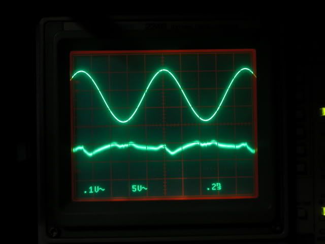
Regarding my Notch filter (2 posts above), with more careful dial adjustments, most of the fundamental is removed....
BEFORE: http://i5.photobucket.com/albums/y177/Midiot/DSCN2745.jpg
NOW:
=RR=
Keep up the progress jackinnj, I will be trying similiar tweaks to my older oscillators. In fact, I just bought an Amber 5100 oscillator, which I've yet to receive.
Schematics, anyone ???
-----------------
Regarding my Notch filter (2 posts above), with more careful dial adjustments, most of the fundamental is removed....
BEFORE: http://i5.photobucket.com/albums/y177/Midiot/DSCN2745.jpg
NOW:
=RR=
Armint, I built the analyzer many years ago, and IMO the design is a masterpiece. No troubles with the oscillator, and my guess is you've got a wrong component value somewhere affecting the gain. Did you do a resistor check with a DVM? I'm assuming you used the pcb layout, not hand wired. When the article was originally published in Audio, there were some followup letters to the editor, with minor corrections/construction points. Don't know if those are on-line or not. Hopefully Bob will chime in with ideas.
> there were some followup letters to the editor, with minor corrections/construction points.
It is not on Bob's site.
If you would have them could post them here, I am sure it would be most appreciated.
Cheers,
Patrick
It is not on Bob's site.
If you would have them could post them here, I am sure it would be most appreciated.
Cheers,
Patrick
I took the output amplifier out of my spare Boonton -- changed out the filter caps which were 100u/25V to some 220u/35V and bypassed with Wima 100nFs -- the THD% of the output amplifier alone is 0.0005% to 0.0006% across the audio spectrum.
Clearly there are a lot of nasties floating around in the Boonton cabinet.
Clearly there are a lot of nasties floating around in the Boonton cabinet.
An externally hosted image should be here but it was not working when we last tested it.
That amp is quite good especially considering how simple it is and it will drive 50 Ohms to 16V RMS.
I can get .0007% loopback on most of my Boontons with careful adjustments, only source grounded and signal into the - input.
I have one with a frequency stability problem but I have decided to sell it rather than have it bug me. With three working ones its really extra.
Is the analyzer side working right?
What is the nature of the distortion in the oscillator?
I had problems with one that related to an inadvertant connection between the ground of the oscillator and the chassis. Since the whole oscillator circuit floats and one output can be tied to the chassis there are many strange problems that need to be checked.
1audio said:
What is the nature of the distortion in the oscillator?
There is a broad band of noise on the Test Pin of the A7 card -- looks to be in a range of 20 kHz to 30 kHz -- and there is quite a bit of power supply artifact -- could be a ground loop problem as you suggest.
Well, just to let you guys know, I started replacing components in the agc circuit of the oscillator and it started working after I replaced the transistors in the detection circuit. I am now going to continue with the rest of the analyzer.
I'm going to ask a very basic question, that I'm sure is so easy, I will be embarrassed when seeing the answer....but I gotta ask....
When a spec is given as:
THD +Noise..... -100 dB
....how does one derive a % number....the THD% we commonly see in most specs ?
=RR=
When a spec is given as:
THD +Noise..... -100 dB
....how does one derive a % number....the THD% we commonly see in most specs ?
=RR=
redrabbit said:I'm going to ask a very basic question, that I'm sure is so easy, I will be embarrassed when seeing the answer....but I gotta ask....
When a spec is given as:
THD +Noise..... -100 dB
....how does one derive a % number....the THD% we commonly see in most specs ?
=RR=
dB expresses a ratio - so does % 🙂
120db = 10^6:1 or 1million :1 or 0.0001%
60dB = 10^3:1 or 1000:1 or 0.1%
etc
Redrabbit looks up dB formulas on the internet, and his right brain says to him......
" ....hey, hey buddy...um, where do you think you're going?.... get back here!
  "
"
=RR=
"
....hey, hey buddy...um, where do you think you're going?.... get back here! "=RR=
Hi, i have carefully read, and build the RodElliot #52 LINK Distortion analyzer, i will use it for meassuring distortion on some of my diy power/pre-amps. But there are few things i can't figure out.
I am totally, confused about howto use it, after reading it over, a couple of times (more), so therefore i was hoping someone here could help me.
I have made the notch filter, for the following freq. :
408Hz, 995Hz, 4,08KHz, 9,95KHz.
The supply i am using is 2x12v batteries, to give me Ref. / +12vdc / -12vdc.
the opamp i am using is LM833, which operates with +12 / -12vdc according datasheet.
all resistor's, caps are meassured for 1%.
I tried to apply 4v ~1KHz sine directly to the notchfilter, and some nice sine also come's out of the notch. I can regulate the sine/voltage-out etc... so i think the nottchfilter work's, i simply can't figure out howto use it
I have a 20Mhz dualchannel oscilloscope, but only 1 probe at moment, for meassuring.
i have following quistion's :
1. One one of the last pages, the instructions howto use it, say's
2. Do i have to apply the signal from my sinegen. (4vac ~e.g 1KHz) into the notchfilter, or into the preamp ???.
If any, can help me further on, i would really appreciate it. I really find it hard to understand.
Jesper.
I am totally, confused about howto use it, after reading it over, a couple of times (more), so therefore i was hoping someone here could help me.
I have made the notch filter, for the following freq. :
408Hz, 995Hz, 4,08KHz, 9,95KHz.
The supply i am using is 2x12v batteries, to give me Ref. / +12vdc / -12vdc.
the opamp i am using is LM833, which operates with +12 / -12vdc according datasheet.
all resistor's, caps are meassured for 1%.
I tried to apply 4v ~1KHz sine directly to the notchfilter, and some nice sine also come's out of the notch. I can regulate the sine/voltage-out etc... so i think the nottchfilter work's, i simply can't figure out howto use it
I have a 20Mhz dualchannel oscilloscope, but only 1 probe at moment, for meassuring.
i have following quistion's :
1. One one of the last pages, the instructions howto use it, say's
Well, do i have to use the potmeter VR1(50k) for this, and set it to lowest output ???.To measure the distortion, set Q to minimum, all tuning pots to the mid position, and frequency to something well away (> one decade) from the intended measurement frequency. With the input level at minimum, apply the signal to be measured. The voltage must be greater than 3V RMS.
2. Do i have to apply the signal from my sinegen. (4vac ~e.g 1KHz) into the notchfilter, or into the preamp ???.
If any, can help me further on, i would really appreciate it. I really find it hard to understand.
Jesper.
Attachments
The principle is simple even if Mr. Elliot slid right past it. Distortion it the measurement of the ratio of wanted (fundamental) to unwanted (harmonics) When you have everything working you would first measure the fundamental level (and this assumes your frequency response is pretty flat) so you detune the oscillator away from the notch to see what level it is. Then you tune the oscillator to the notch and tune the notch to the oscillator until you get a null, (and as he said it will be very unstable and drift constantly) and once you have it nulled (lowest level) that voltage's ratio to the first measurement is the distortion.
Or you get a used distortion analyzer (the more recent ones are very good, easy to use and not too expensive in the US) and its all almost automatic.
Or you get a used distortion analyzer (the more recent ones are very good, easy to use and not too expensive in the US) and its all almost automatic.
I havent read this R. Elliot thing yet but maybe my comment will help a little. The idea here is to feed a clean undistorted sine wave into your "device under test"(preamp). I have a couple H.P. units that aren't bad. Then, you look at the output of your D.U.T. (device under test) with your distortion instrument(s). You measure the level for a baseline. You use the notch filter, as part of your distortion measurement set, to get rid of, remove, the sine wave that is comming from your D.U.T.. If there were no output from your filter(your notch filter would have to be perfect for this to be true) you would be measureing 0.0% THD +noise. You would have "nulled" the fundamental (the sine wave) and you would not be measureing any harmonics generated by your D.U.T.. Also, no output would indicate 0 noise volts. 😀
Truth is, its difficult to build a notch filter that can actually null your sine wave much beyond 60db or so without causing it's own problems(more distortion, etc.). So, you will see the sinewave coming out of the notch at some much reduced multiple. 60db is 1/1000th lower signal than your baseline measurement. Or, .001%. But, you are looking for harmonic distortion. That would be 2X, 3X, 4X, etc. the freq of your sine wave. The notch is not tunned to the higher harmonics so you can measure them with an RMS voltmeter. They should be a higher level than the fundamental sine wave freq. at the notch output.
One other "truth is", you likely wont know weather you are measureing 2X, 3X, 4X, etc harmonics, or the noise of the circuit. Hence the "THD + noise" designation.
Probably just confussed everyone more
flg said:I havent read this R. Elliot thing yet...
Truth is, its difficult to build a notch filter that can actually null your sine wave much beyond 60db or so without causing it's own problems(more distortion, etc.). So, you will see the sinewave coming out of the notch at some much reduced multiple. 60db is 1/1000th lower signal than your baseline measurement. Or, .001%. But, you are looking for harmonic distortion. That would be 2X, 3X, 4X, etc. the freq of your sine wave. The notch is not tunned to the higher harmonics so you can measure them with an RMS voltmeter. They should be a higher level than the fundamental sine wave freq. at the notch output.
One other "truth is", you likely wont know weather you are measureing 2X, 3X, 4X, etc harmonics, or the noise of the circuit. Hence the "THD + noise" designation.
Probably just confussed everyone more
Use the "Function Out" for your DA and hook it into a spec analyzer, even a sound card based one -- and you can measure the magnitude of each harmonic.
RMS detectors, even the venerable AD536, have their shortcomings...
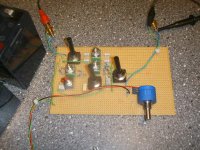
My Notch:
http://i5.photobucket.com/albums/y177/Midiot/DSCN2753.jpg
http://i5.photobucket.com/albums/y177/Midiot/DSCN2748.jpg
http://i5.photobucket.com/albums/y177/Midiot/DSCN2749.jpg
Rod Elliot's project is a good learning experience. I have a full dist meter, but this diy project was kinda fun for me, anyways.
The switches will "tune" the notch, the pots in Fig. 5, will fine-tune it.
So for the first step, you want to apply a signal freq that is NOT in the freq range of any combination of those switches (de-tune the notch). You don't want to notch (filter) anything for the first step.
Try this using your sig gen only (sine wave). You can insert your preamp (DUT) later, between the sig gen and filter, after you get the hang of it. So for now, you will be measuring the dist of your sig gen.
The first step is to apply a higher voltage freq at the INPUT, and get a lower voltage at the OUTPUT of Rod's filter.
How I do it, is measure the sig gen at it's output, and adjust it to say, @ 4v AC. Turn Q (50k output pot) all the way down.
Connect your sig gen (@4v) to the filter's INPUT. measure the AC volts at the filter's output. Adjust the input pot (10k) until the filter's OUTPUT reads 3v AC.... then don't touch that 10k pot, leave it alone for the duration of the test.
Disconnect the AC meter, and connect the filter's OUTPUT to your scope. You should see a 3v sine wave.
(you can add a splitter at the sig gen output to see "before/after"...one cable to the filter, other to your dual input scope.)
Move the Q pot to mid-way.
Now set the switches to your frequency you want to notch, and make sure your sig gen is set to that freq too. Use "Table 2" to see what position to set the switches.
If you are lucky, you'll see the sine wave reduced. But maybe not.
This is where the fine tuning happens....and this filter is ALL ABOUT the fine tuning!!
In a perfect "Twin-T" filter, all the resistors and caps are perfectly matched to each other in terms of ratio. Highly unlikely in our case. That's the pots' job now....to match up the resistors. The cap matching is what it is.
Caveat: it is EXTREMELY helpful to have a "fine tune" knob on your sig gen.....this helps you "find" the notch, and tune it as well.
I found that my notch filter's range was not what Rod's article stated....but it was close, up or down 5% or so. That is why the sig gen fine tune knob helps. You need to do a little (or a lot) of hunting for the notch. Turning the Q knob down will help you find the notch.
When you seem to have found the notch, it will still need more fine tuning. Raise the Q knob. Fiddle with the filter's pots to reduce the sine wave. Then the "fine tune" on your sig gen, then back and forth until you cannot get it any lower. You want the Q knob all the way up by the end of your fiddling.
Then use the equation in Rod's article, to find dist %.
This is not low enough:
http://i5.photobucket.com/albums/y177/Midiot/DSCN2745.jpg
This is better:
http://i5.photobucket.com/albums/y177/Midiot/DSCN2764.jpg
See my ESP forum thread:
http://sound.westhost.com/phpBB2/viewtopic.php?t=1788
=FB=
Forgot to mention...
...when fine-tuning the filter, run the output to an AC voltmeter (to read millivolts) then when it won't go any lower, switch to the o'scope to view it.
The voltmeter will "show" you a better indication of the reduction (deepest notch).
=RR=
...when fine-tuning the filter, run the output to an AC voltmeter (to read millivolts) then when it won't go any lower, switch to the o'scope to view it.
The voltmeter will "show" you a better indication of the reduction (deepest notch).
=RR=
Henry Pootel said:What about using this to put one together?
http://focus.ti.com/docs/toolsw/folders/print/ads1271evm-pdk.html
It comes with some software to measure THD and costs $149.
I am not sure if there is an API that you can use for your applications (what I would prefer).
I hope this helps.
About 2 years later I finally got this working -- it had been sitting on the shelf next to my work station -- shown is the output from a Tektronix programmable SG505 -- the THD+N on the screen works out to be the same as that measured on my AP. When I measured the output from my AP the THD was -112dB. (Edit, it will get to -116dB momentarily).
The "package" from Texas Instruments includes an MMB0 motherboard with a TMS320 DSP processor -- and the software packaged with the unit allows this one screen only although you can change the type of FFT window and whether to use high speed or high accuracy. For $149 it ain't bad
The ADS1271EVM has a pair of very low noise differential amplifiers, (OPA1632 -- 1.5nV/RtHz) but you can't run a signal much more than 1.8VRMS into the thing.
An externally hosted image should be here but it was not working when we last tested it.
I've got one of those, but I havent gotten around to setting it up.
Any hints you'd care to share?
Any hints you'd care to share?
TI just sent me the schematic for the MMB0 motherboard -- apparently your going to need their Codesource program --
The CD-ROM has some hints on setting up the power supply for the motherboard -- I used +/- 15V on the analog power and 5V for the DSP processor and associated stuff. The opamps have differential inputs -- so I ran them from the balanced outputs of the AP and SG5010 -- there is a schematic of the ADS1271EVM on the CD-ROM but it isn't on TI's website.
There is an error in high resolution mode -- the frequency displayed is cut in half.
What do you think about µcontroller (PIC, ATMega..) based function generators and distortion analyzer etc?
Expensive modern measure equipment is probably based on good hardware and software platform, and software is basically a heart of performance.
Well OK, they use more powerful microprocessors and software, but micro controller is pretty powerful and versatile thing if it´s filled with good program.
Expensive modern measure equipment is probably based on good hardware and software platform, and software is basically a heart of performance.
Well OK, they use more powerful microprocessors and software, but micro controller is pretty powerful and versatile thing if it´s filled with good program.
- Status
- Not open for further replies.
- Home
- Design & Build
- Equipment & Tools
- distortion analyzer recomendations?