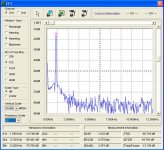
Here's an FFT using the TDS3012B -- the MATH (red) --- I used my Wavetek sweep generator which isn't particularly clean to demo the point -- i'm sure you know all about taking the square root of the sum of the squares -- the distortion plus noise is about equal to what I get on the "FUNCTION OUT" of my Tektronix AA501:
Fundamental -- measures 398mV
Magnifying the distortion components to 2mV/div
Fundamental -- measures 398mV
An externally hosted image should be here but it was not working when we last tested it.
Magnifying the distortion components to 2mV/div
An externally hosted image should be here but it was not working when we last tested it.
Hi,
I'm just playing with a DSO-2150USB. I don't know that much about it yet, but it seems to be pretty good. For $200 ish - no complaints.
I have attached a capture of the output of my HP 339A in FFT mode. There is a lot of noise (could be from simply hooking things up in the open). I do notice a 100 MHz emission from it as well.
Anyway, I'm going to keep it. Money reasonably well spent I think.
-Chris
Attachments
Oscilloscope questions
Jack,
Thanks for the info and demo. I have both the TDS3032B and TPS2014 here, and am going to sell one of them. I am pretty sure I will keep the 3032B because of the increased bandwidth and the fact that I don't think I would really use the four channels of the 2014.
What kind of things would the isolated inputs of the TPS2014 be advantageous for? Is there any reason to keep the TPS2014 over the TDS3032B?
Thanks for your time,
Donovan
Thats a fair amount of Digital scope in each of those. The isolated inputs are great for eliminating ground loops or for measuring power stuff. They are so new, and you are already selling one? Must be a good story there.
redrabbit said:Any ideas for a very quiet notch filter ?
Either a pre-made product, or DIY ?
Distortion Analyzer (w/twin T notch filter)
http://sound.westhost.com/project52.htm
=RR=
1audio said:Thats a fair amount of Digital scope in each of those. The isolated inputs are great for eliminating ground loops or for measuring power stuff. They are so new, and you are already selling one? Must be a good story there.
Yupp, you betcha! No triaxial connectors here. I just used my regular pomonas and set up on the bench (which has an anti-static surface -- bought from another electronics defense contractor fleeing New Jersey.)
The TDS3012B is pretty noisy. The 5223 which I own is much, much quieter -- if you want a quiet scope get one of the Tektronix boatanchors. I regret having gotten rid of my 535.
How ya doin' with the new Boonton? FWIW, I put some of the new National Semi OPAMPS in my 1120.
jackinnj said:How ya doin' with the new Boonton? FWIW, I put some of the new National Semi OPAMPS in my 1120.
I know you were speaking to 1audio but.... I also thought of upgrading the socketed opamps in my Boonton 1100.
Factory spec says 0.03 % distortion.
Here's the oscillator schematic....
http://i5.photobucket.com/albums/y177/Midiot/DSCN2734.jpg
http://i5.photobucket.com/albums/y177/Midiot/DSCN2741.jpg
=RR=
Here's the power supply section of the 1120 -- bootstrapped voltage reference and error amplifier:
An externally hosted image should be here but it was not working when we last tested it.
I went through that opamp drill. The sockets are great and so is having the extender board. But it seems the op-amps in the front end are not the real limitation. The noise won't go down much, its limited by the divider resistors, the distortion also doesn't get much better. I can get down to .0007% midband for a few days after tweaking but not further. And there are some artifacts in the distortion that just don't go away. I tried this on three different boxes and they all responded the same.
I do want to experiment with a chopper op-amp for the DC section since that seems to be the limitation in the DC accuracy.
As soon as I can make some room on the bench I should be able to use the Shibasoku to find the source of the distortion. The Shibasoku is 20 dB better so its much easier to see where the problems are. But its also much bigger.
The voltage regulator circuit looks interesting, but I wonder about both stability and noise. The stability of cascading the gain of the regulator and the wide open TL072 and then the noise of the TL072 would set the floor of the system. Probably low enough that the limits are the opamps themselves anyway. And the REF01 is very stable eliminating another adjustment.
1audio said:I do want to experiment with a chopper op-amp for the DC section since that seems to be the limitation in the DC accuracy.
The voltage regulator circuit looks interesting, but I wonder about both stability and noise. The stability of cascading the gain of the regulator and the wide open TL072 and then the noise of the TL072 would set the floor of the system. Probably low enough that the limits are the opamps themselves anyway. And the REF01 is very stable eliminating another adjustment.
Yesterday, for the first time, I was able to get the 1120 oscillator down to 0.00033% -- I used a new Pomona cable and BNC to BNC and a big copper jumper from case to case. With balanced to balanced it was 0.00068% Go figure.
I have an older version of the 1120 Manual -- the power supply in both my Boonton's use 2 REF-10's so it is quite different.
The Boonton which I have as backup has power supply issues -- so I am installing some Mallory CG caps -- 4,500 uF/35 V as the Nichicon's but able to stand more heat. The first Boonton I purchased was recapped by the company (they are about a 20 minute drive from my house.) Here's what's lurking on the supply rails of the driver (A7) board for the oscillator with issues:
An externally hosted image should be here but it was not working when we last tested it.
I have found that the - input is consistently lower distortion. When you say case to case what do you mean? The generator is in the box with the oscillator, unless there is something i missed here.
My manual has rev 1 for the power supply. I can't find my 1130 manual right now but I doubt it will offer much.
The Ref10 is obsolete so I hope for your sake they are OK. The easy way to check the supplies is to pull boards and see if the supplies recover unloaded. If its an early unit (no power amp on the back) the supply is common in to out. The later units have isolated supplies and optocouplers for the buss so the oscillator is completely independent from the analyzer.
I was warned about the dead cap syndrome by Boonton as well. The local surplus store yielded the necessary caps for one unit but it made only a small difference. Checking the ripple will show you all you need to see.
I just checked my 1121 parts machine and the supply (11102800A) uses 2 REF01's so check yours again.
Checking the REF01 and the REF10 data sheet they seem to be interchangeable.
Here is the schematic for the output amp of the Boonton 1120
output amp board
Its good for 16V into 50 Ohms.
Here is the schematic for the output amp of the Boonton 1120
output amp board
Its good for 16V into 50 Ohms.
Thanks, Demian.
Working with the 1120 reminds me of a Gene Wilder line from "Young Frankenstein"
"I've got it, change plus to minus and minus to plus" --
I am thinking that the analog power supply should go in a separate carcase, and that perhaps some of the digital stuff should have better shielding.
Working with the 1120 reminds me of a Gene Wilder line from "Young Frankenstein"
"I've got it, change plus to minus and minus to plus" --
I am thinking that the analog power supply should go in a separate carcase, and that perhaps some of the digital stuff should have better shielding.
I don't think performance imporvements will come from the extreme measures you are proposing. The limitations are synchronous to the signal so we should look for causes that are synchronous. I always see some little HF blip syncronous to the incoming signal. And there are so many stages handling the signal to the notch filter as well as the linearity of the notch filter to think about.
The places to look for syncronous stuff are the agc detector in the oscillator and some of the other similar functions. The AD536 on the filter board can contribute as can the phase detectors on the notch board.
For straight distortion there are 5 single opamps (ne5534's) and 3 dual opamps on the notch board. Plus the impact of the cmos switches etc. I have played with a lot of them with only a small improvement.
The noise floor is partly limited by the series resistors on the input board- 10K minimum- which sets a finite floor on the noise. Without them the issue is fried input amps.
No easy solutions. And without a much better source its hard to know if you are making progress.
1audio said:
The places to look for syncronous stuff are the agc detector in the oscillator and some of the other similar functions. The AD536 on the filter board can contribute as can the phase detectors on the notch board.
The AD536 is problematic in and of itself -- I have been playing around with the LTC1966 and LTC1968 and they are much, much more acurate and faster.
I simulated the output amplifer -- shouldn't be much contribution from that part of the device.
One of my Boontons doesn't have the amp and does have the same distortion floor.
The AD536 is old. And that is an area where much progress has been made. The best solution is still the thermal converters but for something like this the new LTC parts may be a significant improvement. Perhaps we can make a little board to allow for substitution. However we need to check to see if the Boonton uses the db output.
The AD536 is old. And that is an area where much progress has been made. The best solution is still the thermal converters but for something like this the new LTC parts may be a significant improvement. Perhaps we can make a little board to allow for substitution. However we need to check to see if the Boonton uses the db output.
Hi guys,
I started building the Cordell distortion analyzer, But I ran into a problem with the signal source, maybe somebody here can help me with it. When I turn on the power, it seems to be working, I get a nice sine wave on the output, but after about half a minute it suddenly stops. I have notices that the amplitude of the signal goes down very slowly to about 90 percent of it's original value, and then it suddenly stops oscillating. If I look at the error signal in the a.g.c. circuit, that one goes down too (but faster than the output signal) and when it becomes a flat line, the entire circuit stops working.
When I then turn off the power and turn it on again, it starts oscillating again, but for a much shorter period. I have to really let it cool down (or discharge?) before it works again for about half a minute. I replaced the opamps and the capacitors in the agc circuit, and some of the other components, but nothing seems to solve the problem. Does anybody have a suggestion what can be wrong here?
thanks,
Armin
Why don't you email Mr Cordell via the forum and ask for his advice (he frequents the Solid State Forum) ?
Please keep us posted of progress.
Patrick
Please keep us posted of progress.
Patrick
I've built a Notch Filter, from Rod Elliot's site.
It seems I can reasonably measure distortion with just this filter and am AC volt/millivolt meter.
...although I intend to use it to improve the dynamic range on my older Spectrum Analyzer.
Here (again) is a link to his project:
http://sound.westhost.com/project52.htm
Here is my cross post from Rod's forum:
I thought I'd share this, for what it' worth.
=RR=
It seems I can reasonably measure distortion with just this filter and am AC volt/millivolt meter.
...although I intend to use it to improve the dynamic range on my older Spectrum Analyzer.
Here (again) is a link to his project:
http://sound.westhost.com/project52.htm
Here is my cross post
from Rod's forum:I've finished it.
It seems to be working.
Can you look at this waveform, and confirm for me?
http://i5.photobucket.com/albums/y177/Midiot/DSCN2745.jpg
Frequency (around 1k) is directly from my function generator.
The upper waveform is the unfiltered signal...and the lower is the filtered output of that waveform, using Rod's Notch Filter (P52).
(note: the upper waveform is a 5v reading, the lower is a 0.1v reading.)
I believe my function generator (the source) is about 0.2% THD, according to the manual.
I'm still not to sure about the grounding. Right now, everything is grounded to the case......BNC IN/OUT jacks, pot ground tabs, and the PSU 0v. But nothing is grounded to earth. When rack-mounting this, to eliminate an earth-ground, I can use plactic screws and washers if it ever becomes an issue.
I found that using an analog AC millivolt meter at the output....allowed me to dial-in the lowest setting, then switch to the O'scope to view it.
----------------------
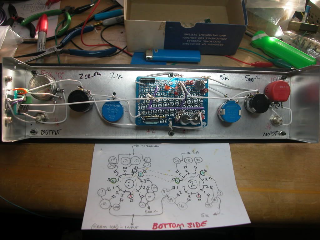
I used two 3-pole, 3 position rotary switches attached to a circuit board. This is like "air wiring" them, because they are point-to-point wired, and the board is just a means to support them.
I probably went overkill on the 10-turn pots. I don't think I needed 4 multiturns (2k & 200 ohm, 5k & 500 ohm)...I could have gotten away with 2 standard pots (2k, 5k) ant only two multiturn (200 ohm, 500 ohm). With 4 multiturns, the smaller ohm-ed pots don't do much.
The 10k input pot is a 1 watt wirewound, the 50k "Q" pot is a good carbon type, both single turn.
The dual opamp is an OPA2134PA.
Power supply is outside the case (not shown).
Here are some pics of the finished unit.
(I still need two knobs !!)
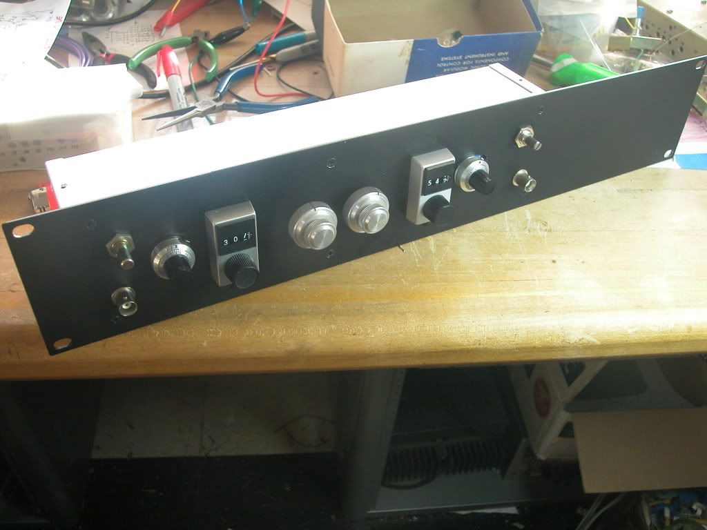
close-ups:
http://i5.photobucket.com/albums/y177/Midiot/DSCN2749.jpg
http://i5.photobucket.com/albums/y177/Midiot/DSCN2752.jpg
I thought I'd share this, for what it' worth.
=RR=
I have a spare Boonton which I just recapped -- this brought the ThD+N% down from ~2% (ouch) to 0.2% -- more bad stuff going on in this piece of equipment -- problem seems to be in the power supply section for the output amplifier -- the oscillator which feeds the final amplifier is registering only 0.0009% -- and this could probably be cleaned up a bit as well.
Here's a view, the dBm/div is the same for both, but the reference levels are different:
Here's a view, the dBm/div is the same for both, but the reference levels are different:
An externally hosted image should be here but it was not working when we last tested it.
- Status
- Not open for further replies.
- Home
- Design & Build
- Equipment & Tools
- distortion analyzer recomendations?