Forgot to reply to this earlier:
I know that the Axe-Fx II (and later) and Line6 Helix amp models do include bias excursion. In fact, the amount of bias excursion is a tweakable parameter with those products. This section of the Fractal Audio forum has some info about what is modeled in the Axe-Fx II and III.What I don't know is if there is or has been any DSP coding done for dynamic bias shifting

You are right.By the way, i've read it would be recommended to have a series resistor with every diode cause op-amps aren't really that good at driving 30...60 ohms dynamic impedance
Driving clippers, which by definition are a short across the source above a threshold voltage, from voltage source, is BAD Engineering.
Some do anyway 🙄 , or use unsuitably low series resistors (say 100-200 ohm), needlessly stressing the Op Amp, pulling unneeded current peaks from supply, etc.
Thank you for your reply! That is certainly a good insight as to why some amp models on the first Axe-Fx series felt static and flat in their responses. At the time it came out, a friend of mine sold his Mesa Stilleto stack for the Axe Fx I. I gave it a run through and it was good but not $3K good. Definitely a big jump from Line 6 and Rack Eleven products at the time. He since changed to a series 2 or 3 floor version. Yeah the models are very good, I could hear a big difference in the liveliness of the sounds.Forgot to reply to this earlier:
I know that the Axe-Fx II (and later) and Line6 Helix amp models do include bias excursion. In fact, the amount of bias excursion is a tweakable parameter with those products. This section of the Fractal Audio forum has some info about what is modeled in the Axe-Fx II and III.
It's quite intriguing to think about the bias shifting and what effect it has on an amps response. There are tube amps that have more gradual onset of distortion, are more lively sounding than others. I can think of a few amps with cathode biased output tubes vs fixed bias, for example..how this can change the overall response.I'm rather surprised at just how crude the early Line 6 modelling (referenced in that link) was. No wonder their stuff sounded so bad!
Line 6 promised a dozen glorious vintage tube amps in a box, but what you actually got was a dozen different types of kazoo in a box.
I was naive enough to fall for the advertising, and the widespread applause on Internet forums, three times. I wasted a lot of money, and a lot of time, trying to get any kind of sound I liked out of any of these horrible products.
Fool me once, shame on you. Fool me twice, shame on me. Fool me three times? I must be a right royal idiot.
Agreed. Even the simple op-amp diode clipper circuit can do this. Plunk down, say, an LED in one direction, a silicon diode in the other. Add a resistor in series with one of them to alter the transfer function slope when that diode conducts. Et voila, asymmetric S-curve transfer function.
Which, unfortunately, tends to produce the same crude buzzing kazoo sounds as the early Line 6 products. 🙁
I can hear duty cycle modulation from the little Flamma Preamp. Whether this was achieved by simulated dynamic bias shifting, or the DSP code implements the same effect in some other way, I don't know.
One way to do that is to square the individual signal sample values (you'd have to subtract the mean, the DC bias value at the input of the A/D converter). That would give you a string of positive numbers, each the square of the instantaneous signal voltage. Then average several of the squared samples together, and you have the mean square value for the signal. Shift out samples and repeat...
Maybe just tweak the coefficients of the appropriate polynomial dynamically? I think that would do the trick, too.
Back in the mid 1980s, John Murphy figured out one way to do this using an op-amp, a couple of diodes, and a capacitor. His circuit is also an op-amp/diode clipper, but the output duty cycle doesn't stay frozen - it shifts with signal level. Murphy used his patented circuit block in many early Carvin guitar amplifiers he designed.
I think I still have a few schematics of those old Carvin amps saved on my home PC. I'll see if I can find one of them when I get home tonight.
To me, Murphy's circuit, while better than the typical diode clipper, is still lacking compared to a good tube guitar amp in overdrive. The smooth progression from "valvey" clean tone to rich distortion is lacking. Clean tones are still sterile (too clean), and even the overdrive has a sort of clinical quality to it. It's not rich and lush like a good tube guitar amp.
I think so, too.
I haven't had the opportunity to play through high-end pioneer digital amp modellers (Kemper, AxeFX, etc). But I listen to videos showcasing these and similar products on Anderton's Music You Tube channel, among others.
A lot of the time, some of the very expensive modellers sound very realistic to me. Unfortunately, this isn't always the case. A Fender Tonemaster digital amp will set you back over $1000 CAD (twice that in some cases), and in online tests, every now and then you can hear the carefully crafted simulated sound fall completely apart, and for a split second, it sounds like a cheap and nasty analogue solid stage practice amp.
Anderton's Music has videos of many relatively affordable (not as eye-wateringly expensive as AxeFX, etc) digital amps, and digital multiFX pedals (all of which include amp modelling now). Some of these have brand names that are relatively unfamiliar (Valeton, Hotone, Nux, etc).
It's interesting to listen to these. Every single one is far, far, far better than the early Line 6 crap. But none of the affordable ones grabbed my ears to the point where I thought "I want to shell out the Canadian equivalent of 300 British pounds for one of those!".
For me, the little Flamma FS06 Preamp is still bang-for-the-buck champion, by far. It has no built in FX pedals, all it does is emulate seven different tube amps, with a clean and dirty channel for each. The FS06 lives on my pedalboard now.
This was one thing that impressed me about the Fender Mustang Micro. It runs on a single internal lithium cell (4.2V at full charge), meaning the internal DSP probably runs at the now-common 3.3V DC.
In spite of the low supply voltage, I can't hear any audible harshness from it (set to clean tone) with any of my guitars played in a reasonable way. Neither the analogue input buffer, nor the A/D converter, overloads in any audible way. Props to Fender for getting that right!
(The amp models are nowhere near as good as the ones in the Flamma FS06, though, even though the Mustang Micro costs considerably more.)
-Gnobuddy
For coding or op amp implementation it would be very interesting to discuss this and the Murphy circuit.
The power supply can be partially responsible for this. In a typical tube amp, it's a non-zero impedance DC source. The original designers of tube guitar amps picked capacitor values, resistor values and the artists played them. Their sound got recorded and it's what everyone cherishes. I'm pretty sure whomever originally designed those amps didnt think about "power supply collapse" - they just designed and built something with appropriate values according to the SOTA at the time.It's quite intriguing to think about the bias shifting and what effect it has on an amps response.
If you look at a tube amp power supply, it's basically a string of RC, with taps on each C feeding the various tube stages in the gain structure signal chain. When the amp is pushed, the first to go down in voltage is the C feeding the output tubes. Since these RCs are relatively large time constants, there's a delay of this voltage collapse by the time it makes it all the way through to the input tube. With the artist particularly rockin', now there's a dynamic load on the power supply output and consequently the power supply moving about in voltage at all points in its RC chain.
When someone invents something like "dual rectifier" as an amplifier feature, that - if the name actually has anything to do with the circuit - changes the output impedance of the power supply. Now for each switch setting the voltage collapse behavior is different, which presumably is picked up by the artist in how the amp sounds as s/he plays.
It's not that hard to make a DC power supply with a fully variable output impedance, as it isnt that hard to make a string of RC filters with variable time constants. Presenting such a mess to a playing artist with the idea that they can change how their amp behaves using all these controls would be what's hard. A or B is easier to grasp, as in "Dual Rectifier".
Now, let's say you have some little nifty Jfet circuit that is doing nicely in its sound, as a guitar preamp. Have you incorporated bias shifting due to power supply collapse in your design? That would give it a dynamic tone response as the bias points move about, following variations in the power supply value, due to changing load as one plays. Key concept; changing load. Where's you changing load in a jfet preamp?
Or, one could take the control voltage part of an auto-wah (think Jerry Garcia sound) and use it to modulate the power supply values directly. One for each stage in the gain structure, each having a different time constant. But better be careful about stepping on someone's patent, as I'm sure that idea has been thought of already -
I don't remember if this has been mentioned already, but as some of you use LTSpice:
A nice feature of LTSpice is that it can import and export wav files. If you can make some completely clean electric guitar recording, you can process it with a virtual circuit, export it and listen to it. If you have some particular nonlinearity in mind and don't quite know how to implement it, you could use nonlinear controlled sources at first and only need to worry about implementation issues if you like the sound.
A nice feature of LTSpice is that it can import and export wav files. If you can make some completely clean electric guitar recording, you can process it with a virtual circuit, export it and listen to it. If you have some particular nonlinearity in mind and don't quite know how to implement it, you could use nonlinear controlled sources at first and only need to worry about implementation issues if you like the sound.
I'm actually not sure to what extent the original one modeled bias excursion (if at all). All I know for sure is that the II and later do model it.That is certainly a good insight as to why some amp models on the first Axe-Fx series felt static and flat in their responses.
I can say from experience that it can make a considerable difference (depends on the amp in question, I'm sure). A couple years ago I designed and built a solid state circuit which reasonably accurately emulates the behavior of the old non-master Marshall designs, including bias excursion of each stage and the power supply sag. As an experiment, I disabled the phase inverter bias excursion modeling and found that it made a marked difference in the sound and 'feel'.It's quite intriguing to think about the bias shifting and what effect it has on an amps response.
I did get some interesting results with the 3 stage fet preamp, using RC voltage droppers along the voltage supply, which was also supply the power amp stage. The preamp is really fussy about supply stability..I probably could have improved this, reducing the effect. But there is some coupling going on the with the voltage supply, especially with 3 stages. Tubes do this as well, usually the first two stages get along but having a third without decoupling on the power supply..well that's the interesting part.The power supply can be partially responsible for this. In a typical tube amp, it's a non-zero impedance DC source. The original designers of tube guitar amps picked capacitor values, resistor values and the artists played them. Their sound got recorded and it's what everyone cherishes. I'm pretty sure whomever originally designed those amps didnt think about "power supply collapse" - they just designed and built something with appropriate values according to the SOTA at the time.
If you look at a tube amp power supply, it's basically a string of RC, with taps on each C feeding the various tube stages in the gain structure signal chain. When the amp is pushed, the first to go down in voltage is the C feeding the output tubes. Since these RCs are relatively large time constants, there's a delay of this voltage collapse by the time it makes it all the way through to the input tube. With the artist particularly rockin', now there's a dynamic load on the power supply output and consequently the power supply moving about in voltage at all points in its RC chain.
When someone invents something like "dual rectifier" as an amplifier feature, that - if the name actually has anything to do with the circuit - changes the output impedance of the power supply. Now for each switch setting the voltage collapse behavior is different, which presumably is picked up by the artist in how the amp sounds as s/he plays.
It's not that hard to make a DC power supply with a fully variable output impedance, as it isnt that hard to make a string of RC filters with variable time constants. Presenting such a mess to a playing artist with the idea that they can change how their amp behaves using all these controls would be what's hard. A or B is easier to grasp, as in "Dual Rectifier".
Now, let's say you have some little nifty Jfet circuit that is doing nicely in its sound, as a guitar preamp. Have you incorporated bias shifting due to power supply collapse in your design? That would give it a dynamic tone response as the bias points move about, following variations in the power supply value, due to changing load as one plays. Key concept; changing load. Where's you changing load in a jfet preamp?
Or, one could take the control voltage part of an auto-wah (think Jerry Garcia sound) and use it to modulate the power supply values directly. One for each stage in the gain structure, each having a different time constant. But better be careful about stepping on someone's patent, as I'm sure that idea has been thought of already -
Great point. And I have seen a lot of commercial designs that didn't pay attention to that detail. Have you listened to an op-amp driving a 200 ohm load or less? Even without a clipper, unless it's designed as a driver, it sounds horrid.You are right.
Driving clippers, which by definition are a short across the source above a threshold voltage, from voltage source, is BAD Engineering.
Some do anyway 🙄 , or use unsuitably low series resistors (say 100-200 ohm), needlessly stressing the Op Amp, pulling unneeded current peaks from supply, etc.
A little over thirty years ago I had a role investigating a batch of misbehaving EFTPOS machines. The root cause was driving an opamp straight into a capacitive load.And I have seen a lot of commercial designs that didn't pay attention to that detail.
The amazing thing was it took four other screw-ups over several years before the machines stopped working. The final straws were substituting the opamp (with a much cheaper one) and then cludging the factory test software to "make it work".
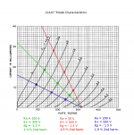
I have a lot of catching up to do but this graph may be of more use.Before we all go too far down the road of creating increasingly complex BJTs together, to create increasingly complex circuits that have rather tightly curved nonlinear transfer functions, I thought that it might be helpful to remind ourselves what the transfer function of the most commonly used preamp tube actually looks like.
The attached image is taken from the datasheet for a 12AX7, and shows the curves for one of the two vacuum triodes it contains.
Note how very subtle the curvature is. This is what we need to reproduce if we want a solid state guitar amplifier to be capable of sounds similar to a valve one.
Tightly curved transfer functions shift abruptly from "too clean" to "too dirty", and that's the problem with all these BJT-based circuits. Everything we can do with diodes iand BJTs s hamstrung by the fact that diodes have such a sharp curvature to their transfer function.
-Gnobuddy
Umm, does that mean for guitar, you want the signal down in the curvy part, vs the straight part?but this graph may be of more use.
That happens in a starved triode preamp, such as in Real Tube distortion pedals, fed meager 9V to 12V rails; now in a normal preamp, you drive it hard so it reaches clipping; top peak will be flattened when it reaches +B ; bottom one will be rounded and never actually reach ground.
Part of "tube sound".
Designers play with that and choose idle bias so when swinging hard it reaches top first, bottom first, different degrees of symmetry or asymmetry, etc.
It´s a complex interactive situation, full of nuances, and those thinking "just throwing a tube in the recipe" is enough, should think again.
So, you're going up and down that whole load line, the one at 250V, clipping at each end? Then you could reduce the bias / drive signal combination and at the same time reduce the plate voltage to have the signal ride anywhere on the family of curves in between 250 and 110V. If you compensated for the drive reduction at the output also simultaneously, then you'd have a clean to let's call it "enriched" curve control, via the more continuous bend in the tube curve.you drive it hard so it reaches clipping; top peak will be flattened when it reaches +B ; bottom one will be rounded and never actually reach ground.
It would be cool to have a single knob change the operating point of the tube, while keeping the stage's gain the same
Yes, that´s the "normal" way in Rock/Metal amplifiers smashing plates against rails.So, you're going up and down that whole load line, the one at 250V, clipping at each end?
Except in an old style Fender Black/Silverface intended to be used clean.
In most Guitar amps the first triode is "clean", but only because pickup signal can´t drive it to clipping (above 80-90V RMS) but in later stages it´s the Jungle baby 😉
Yes, but the continuous bend happens at lower voltages, say around 60V or so, swinging some 20V higher or lower.Then you could reduce the bias / drive signal combination and at the same time reduce the plate voltage to have the signal ride anywhere on the family of curves in between 250 and 110V. If you compensated for the drive reduction at the output also simultaneously, then you'd have a clean to let's call it "enriched" curve control, via the more continuous bend in the tube curve.
At high voltages (110 to 250V) curves are quite linear.
It has been done.It would be cool to have a single knob change the operating point of the tube, while keeping the stage's gain the same
In general Guitar Amp designers use brute force methods, they simply add "one extra triode", typically it´s "way too much" (gain comes in 30-40dB chunks) so the fine tuning comes from adding attenuators and some bias tweaking.
And they hardly if ever make it user-adjustable.
The ones who do are the SS designers, who have to sweat their sports shirts to get good designs, a few selected do.
One is the classic SansAmp PSA1 Guitar rack preamp, impressive sounds, it should be "king of the hill" except it´s too complex for the average player who much prefer "plug and play" .... literally.
It has 4 "character" controls , of which "Buzz" does exactly that.

IT starts with midpoint bias, so providing roughly symmetrical clipping if driven, and then it shifts bias radically; at about halfway setting it´s similar to JCM800 cold clipping, and beyond it becomes a string of razor sharp narrow pulses ... you pick and choose what you like.
The SansAmp series is a fine example of good quality, well thought out SS designs. My band mates used both the guitar and bass floor pedals, and yes I thought they sounded quite good.The ones who do are the SS designers, who have to sweat their sports shirts to get good designs, a few selected do.
One is the classic SansAmp PSA1 Guitar rack preamp, impressive sounds, it should be "king of the hill" except it´s too complex for the average player who much prefer "plug and play" .... literally.
At least to me, I am not necessarily that interested to replicate the behavior of an entire "real tube" guitar amplifier. But I think that if we are looking at gradual progression of low order harmonics, dynamic bias shifting (excursion) and multiple stages of lower gain, non-linear responses, then multiplying that out by a few stages for a preamp, and eventually a power amp..well you might get very close to actually achieving it.(Remember we need to simulate 4 - 5 tube stages feeding each other in cascade to replicate the behaviour of real tube guitar amplifiers.)
If it were DSP code, you wouldn't even need to copy and paste the transfer function block of the triode waveshaper multiple times..you could just pass the signal "x" through the same "waveshaper function" call multiple times in a nested loop. Of course you would probably want to treat it, for example pre (bias shift/excursion) and post (filtering and attenuation). One may even want to develop a waveshaper with Pentode-like characteristics, or something entirely new.
This may sound a bit off the wall, but IMHO "DSP for Musical Amplifiers" could probably be an interesting sub-forum here under Live Sound/Instruments& Amps. There are some DSP standalone modules available on the market and especially these days, a lot of tinkerers/DIYers in this field. My C++ is very rusty, same with assembly language..but it's fun to try and learn/create something new. 🙂
In solid state we obviously can't call on the same "waveshaper" circuit multiple times but we can build out multiple waveshaper blocks, and they can be of similar or different designs. I am still working on the simple 3 FET preamp, it's plugged into the Traynor Bloc 100 now as the "Distortion Channel". Much happier with it than the Traynor's original distortion channel, but some little refinements to make on it. Maybe I will post a new thread about it soon. Cheers!
Hi everyone, sorry to keep disappearing. The short version is that I have "long COVID", and most of the time I'm exhausted, achy, dizzy, coughing, weak, confused, and generally sick. This has been going on for about fifteen weeks now, with no real improvement in sight. Some days are a little better, some a little worse, but there's no overall trend towards recovering and starting to feel healthy again.
Since I don't have the luxury of being retired, I also have to keep working, which has been hard on many of my worse days. There have been a lot of days and sometimes weeks, when I was in survival mode, with no extra energy for luxuries such as online forum participation.
When I do finally find a little extra energy to fire up a browser and point it at diyAudio, days or weeks may have passed since the last time I did the same.
I'm glad to see the thread is still quite active and there's lots of discussion going on. The more people realize that Hi-Fi audio and e-guitar audio demand very different characteristics from the electronics, the better.
Last time I was here I mentioned I had schematics for some of the Carvin SX amplifiers designed by John Murphy, which incorporated his patented distortion circuits that create "duty cycle modulation". My ears say that Murphy's circuits are an improvement over crude diode-clipper circuits, but are a long way from sounding as good as an excellent tube guitar amp being overdriven.
And there, in my experience, is the key problem: solid-state analogue audio circuitry tends to produce either Hi-Fi "clean tone", which sounds thin and unattractive with e-guitar, often with a layer of gritty distortion (discussed at the start of this thread), or a heavily distorted raucous buzz simulating a heavily overdriven Marshall tube amp. It's the territory in between those two extremes that tends to be lacking.
I'm attaching two images; one, John Murphy's overdrive circuitry from a Carvin SX amplifier, and two, an image I created starting with transfer characteristics for a half-12AX7 vacuum triode. That image shows estimated second-harmonic distortion at the output resulting from a 2Vpp sinewave input. The point of my calculations was to show that the exact amount of distortion varies with the anode load resistance, but for our purposes here, the key point is that a single triode stage only creates roughly 5% second-harmonic distortion.
Most of the diode or FET circuits we've seen on this thread tend to immediately produce far, far more distortion than that, and that's why they're much better at creating heavily distorted guitar sounds, than very subtly coloured "clean tones" (that contain a few percent low-order THD).
-Gnobuddy
Attachments
That's not a novel observation. In fact I suspect it was a design goal for general-purpose (linear) triodes when 1920s designs were hotted-up in the 1940s. You can bump Gm way up at high current (RF/IF or TV tuner triode) but that increases THD in baseband service cuz low current Gm is less. (FM don't care; AM averages both sides of the wave).the key point is that a single triode stage only creates roughly 5% second-harmonic distortion.
Get well.
- Home
- Live Sound
- Instruments and Amps
- Discussion: Unwanted clipping in solid-state e-guitar preamps