I cloned tube amps only for 6 years and i have some less sweet and more bitter memories about that period in my life, but I reckon there's a danger to have a less skilled theoretical guy like me involved in this discussion...
If I remember right , Jtm45, Fender pro reverb and Vox ac30 have this progressive entering into crunch distortion from absolute clean only from the guitar gain setting and advanced further by raising the headamp's gain...pretty difficult for solid state to have this transition controlled from only one knob without digital interference.Some guitar pickups having higher output can even drive it harder only by singing the notes harder...I think I saw some videos on this qualities of electric guitar signals that can only be tamed through miking, noisegates ,compressors...leading to the ideea that in fact we can't really listen even to a clean guitar sound unless we limit its crest factor or something like that which makes for the Fender's clean boring perception due to its all time lowest gain structure,not good enough for rock...Carvin came in the middle with the most tamed boring drive...so you won't buy Carvin for hard rock, nor you'll find the real Clean on it ..but you'll pay a lot more than you'd pay for a Fender for the sweetness of Steve Vai.. that's if you are in 2010...
Today this bussiness evolved a lot into the digital realm and seeing Quilter's efforts to make an analogue solid state guitar amp that sounds like 1959T Marshall feels only like his late years hobby even if it might be having some merits.He's probably having enough money from QSC to care about the financials of his bussiness anymore.I cloned tube amps up until 12 years ago , today's digital sound banks cloned pretty much every sound of the past...These skills are simply useless applied to guitar realm.
If you're a young guitar player in 2023 you're going to ignore pretty much every technical discussion when you can buy a 2 kg cube that replicates every single tone ever put out by any guitar amp ever built in any miking setup and ambiance ever used once you connect it to a computer with enough VST's in it...
Last edited:
My turn to sigh.Could you actually READ the damn post before replying to it?
Of course I read your post before replying.
Your analysis is incorrect.
Your mistake is that you're not considering the feedback resistor in parallel to the diodes. The current through that resistor alters (lowers) the slope of the transfer function in the region where neither LED is conducting much.
This is why you don't get the abrupt vertical step in the middle that you're predicting, but rather, a linear slope that fades smoothly into a curve at both ends.
The simulation doesn't defy logic, it only defies your present mental picture.I read yours, saw a simulation plot that seems to defy all logic
This happens to all of us - sometimes our internal mental model is wrong, and if we're lucky, we find that it just doesn't match up to reality. (If we're unlucky, we never find out we're wrong, and continue to believe something that is incorrect.)
This has certainly happened to me hundreds of times during the course of my college education, and hundreds of times in conversations with other people, and hundreds of times from reading technical or scientific books.
The mental picture may seem quite reasonable, but it can still be incorrect. This is exactly the reason why experimental verification is part of the scientific method. Logic frequently goes wrong. Reality (experimental verification) tells the truth.
For example, Aristotle was perfectly logical to assume heavier objects would fall faster - after all, whenever you push an object harder, it accelerates faster.
But Aristotle was wrong, all the same. In fact, heavier objects fall at the same rate as lighter ones, except for interference from air resistance. There's a famous old physics experiment in which you put a feather and a penny into a long glass tube, use a vacuum pump to evacuate the tube, seal it, and then turn it over. The feather and the coin fall at the same rate.
Back to our present topic (LTP vs diode-clipped op-amp). I've explained the logic in words already. Let me try it in different words and see if it clicks for you this time:
Remember that the op-amp is configured in a way that turns it into a current source (output current = input voltage/input resistance). The resistor/diode network in the op-amp feedback loop is being fed from a current source.
In my example, input voltage to the clipping stage falls slowly and linearly from a positive value to an equal negative one. Therefore the output current rises linearly from a negative value to an equal positive one.
That output current is shared between three elements - the feedback resistor, and the two antiparallel LEDs connected in parallel with it.
Around the crossover region, current through the diodes is negligible compared to current through the feedback resistor. Since the resistor is a linear element, the output voltage varies linearly with the input voltage in this region. The voltage gain of the circuit in this region is simply (Rfeedback/Rinput), as it is just an ordinary inverting amplifier stage.
As output current increases, voltage across the feedback resistor rises to the point where one of the diodes (the forward biased one) will start to flow some current. Because the op-amp output is a constant current source, current through the resistor will decrease by the same amount.
The nearly exponential current flow through the diodes causes a nearly logarithmic growth in the voltage across the diode - and that's what you see in the output.
Log(x) doesn't slam into a wall - remember d(log(x)/dx = 1/x? The derivative never drops to zero, meaning the function continues to rise slowly with increasing x.
An LTP works very similarly. "Tail" current is constant and divides between the two transistors. As the current through one BJT rises exponentially with increasing signal voltage, the current through the other BJT falls accordingly.
If you stop and think about this, the mechanism really is very similar to the diode clipper. And my intuition said the transfer functions would be very similar with correct choice of feedback resistor.
So is my mental picture of how this circuit works correct, or is it yours? One of them is definitely wrong.
The best way to prove this one way or the other would be to build and measure both circuits. I'm not about to spend the time and money to build either circuit, though you're most welcome to, if you like.
A very good second best is to use a very well tested computer simulation. SPICE was created circa 1970 at Berkeley University. It's been used for over fifty years by scientists, engineers, and students. It's been used millions of times by millions of people. There's no doubt that SPICE itself works very well.
LTSpice is a version of SPICE that was created and used internally by Linear Technology engineers to design chips. Again, LTSpice has been used millions of times by millions of people. It's a very solid piece of software.
Yes, there is the possibility of a flawed mathematical model of one particular LED or diode. The simplest way to test for that is to try another simulated diode. Every model can't be wrong. If you get similar results from multiple virtual diodes, you know the model is decent.
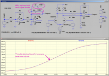
Take a look at the attached screenshot. I've added an LTP, for comparison with the LED op-amp clipper.
Comments:
1) I switched to JFET-input op-amps, to eliminate any errors due to input bias current.
2) The linear ramp to the diode clipper rises from -2V to +2V, as before.
3) The linear voltage ramp to the LTP is differential (V5 is inverted compared to V4).
4) Because the LTP is hypersensitive to voltage, I had to reduce the amplitude of the ramp voltage - it ramps from (-100mV) to (+100mV).
Twenty times smaller than the input voltage to the op-amp diode clipper.
5) I tweaked R9/R10 (gain of the differential amplifier) so that the output voltage from the LTP swings through the same voltage range as the output voltage from the diode clipper, i.e. from roughly (-2.1V) to roughly +2.1V. In other words, I divided down the LTP output voltage to match the characteristics of the LEDs in the other circuit.
6) Finally, I tweaked R3 (the op-amp feedback resistor in parallel with the LEDs) to match the output of the two circuits as close as possible. As I've mentioned a few times, this resistor sets the slope of the transfer function in the crossover region (where neither LED is conducting significantly.)
And the result? See for yourself!
The two transfer functions are virtually identical.
To summarize: a BJT LTP produces a tanh() transfer function. So does a properly adjusted op-amp diode clipper.
-Gnobuddy
Attachments

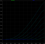
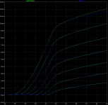
As there might be a difference in behaviour between a red and a white LED, I've repeated my experiment with a white LED of unknown type, also salvaged from a bicycle light found on the street. Due to the higher forward voltage, I had to put my meter in its 20 V range, in which its resolution is 10 mV. That's a bit rough for a diode transfer, so the plots are not as nice as for the red LED.
Voltage-to-current characteristic of the LED:

The orange curve is 45 uA at 2.5 V, a decade per 110 mV (emission coefficient just over 1.9).
The reverse current at 2.9 V was immeasurable with my set-up (< 100 pA).
Resulting current-to-voltage transfer for a white LED with 100 kohm in parallel, calculated using 45 uA at 2.5 V, a decade per 110 mV for the LED:

Voltage-to-current characteristic of the LED:
The orange curve is 45 uA at 2.5 V, a decade per 110 mV (emission coefficient just over 1.9).
The reverse current at 2.9 V was immeasurable with my set-up (< 100 pA).
Resulting current-to-voltage transfer for a white LED with 100 kohm in parallel, calculated using 45 uA at 2.5 V, a decade per 110 mV for the LED:
Your mistake is that you're not considering the feedback resistor in parallel to the diodes. The current through that resistor alters (lowers) the slope of the transfer function in the region where neither LED is conducting much.
Somehow you must have missed this part of post #170: "Using the IF = 25 uA * 10(VF - 1.65 V)/0.093 V model, I then calculated the current versus voltage characteristic of a LED with 100 kohm in parallel with it."
This is why you don't get the abrupt vertical step in the middle that you're predicting, but rather, a linear slope that fades smoothly into a curve at both ends.
What abrupt vertical step? There is a 100 kohm linear slope that flattens off. Vertical: voltage, horizontal: current through the LED plus the current through its 100 kohm parallel resistor.
The mental picture may seem quite reasonable, but it can still be incorrect. This is exactly the reason why experimental verification is part of the scientific method. Logic frequently goes wrong. Reality (experimental verification) tells the truth.
That's exactly why I measured rather than simulated the LEDs!
Remember that the op-amp is configured in a way that turns it into a current source (output current = input voltage/input resistance). The resistor/diode network in the op-amp feedback loop is being fed from a current source.
Of course it is, hence the current at the horizontal axis of my calculated current-to-voltage characteristics.
In my example, input voltage to the clipping stage falls slowly and linearly from a positive value to an equal negative one. Therefore the output current rises linearly from a negative value to an equal positive one.
That output current is shared between three elements - the feedback resistor, and the two antiparallel LEDs connected in parallel with it.
Indeed, and I neglected the < 500 pA of the LED in reverse, but not the 100 kohm resistor and not the LED in forward.
A very good second best is to use a very well tested computer simulation. SPICE was created circa 1970 at Berkeley University. It's been used for over fifty years by scientists, engineers, and students. It's been used millions of times by millions of people. There's no doubt that SPICE itself works very well.
LTSpice is a version of SPICE that was created and used internally by Linear Technology engineers to design chips. Again, LTSpice has been used millions of times by millions of people. It's a very solid piece of software.
Beside the point. I never claimed there was anything wrong with the simulator, rather with the way the LED is modelled.
Yes, there is the possibility of a flawed mathematical model of one particular LED or diode. The simplest way to test for that is to try another simulated diode. Every model can't be wrong. If you get similar results from multiple virtual diodes, you know the model is decent.
A more reliable approach is to compare the simulated voltage-to-current characteristic of the LED you used with measurements.
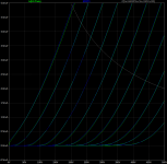
To investigate concerns that the SPICE model of the LED might be faulty, I swapped the LEDs for plain-Jane 1N914s in the op-amp/diode clipper.
After adjusting resistor values to match the smaller output range, once again the two curves match very well - the diode clipper and the LTP both produce virtually the same transfer function.
Conclusion: the type of diodes used in the op-amp clipper will change the peak-to-peak output voltage, but the transfer function will still be a tanh() function provided the op-amp feedback resistor is chosen correctly.
-Gnobuddy
Attachments
The essential difference is that these diodes have far smaller forward voltages than the LEDs you proposed to use. What matters is the ratio of forward voltage to emission coefficient, the smaller that ratio, the smoother the curve will be. Hence my suggestion to try germanium or Schottky diodes.
You're right, I did miss that. My apologies.Somehow you must have missed this part of post #170: "Using the IF = 25 uA * 10(VF - 1.65 V)/0.093 V model, I then calculated the current versus voltage characteristic of a LED with 100 kohm in parallel with it."
I don't want to nit-pick; but the bottom line is that you can indeed get a tanh() transfer function from either an op-amp with clipping diodes, or an LTP. There's no material difference.
Of the two, the LTP circuit is more complex, has vastly inadequate input headroom, and has no advantages over the basic op-amp diode clipper.
In my opinion, neither circuit sounds good when used in an electric guitar amplifier. Both suffer from exactly the same problems - abrupt onset of harsh-sounding distortion, and a monotonous buzzing sound due to the lack of duty cycle modulation in the output waveform.
Very true, but very time consuming, and I don't even have that particular LED. It's probably long out of production.A more reliable approach is to compare the simulated voltage-to-current characteristic of the LED you used with measurements.
If you want to make more measurements, knock yourself out. As for me, I've spent all the time I'm willing to spend on this particular wild-goose chase.
-Gnobuddy
The simulations don't support this statement....the smaller that ratio, the smoother the curve will be...
The curve is equally smooth with every diode type I throw at it, once signal levels and feedback resistor value are adjusted to match.
-Gnobuddy
If you want to make more measurements, knock yourself out. As for me, I've spent all the time I'm willing to spend on this particular wild-goose chase.
-Gnobuddy
I don't. I'm fed up with it and don't want to reply to any of your threads anymore.
Agreed, and clearly, that is the future of guitar amplifiers.Today this business evolved a lot into the digital realm...
IMO, if you want to make your own e-guitar amplifier, it's easier to build an analogue one, than to try and replicate millions of lines of computer code needed to create a good DSP amp model, not to mention the multilayer PCBs, tiny surface-mount components, and plethora of switches, knobs, LEDs, and display screens.
But for mass production, DSP is pretty clearly the way forward.
To me, Fender's "Tonemaster" digital amps look like the company's exit strategy for the day when they won't manufacture any more tube amps. To appease the old guys (like us!), they're putting modern digital amps into vintage-looking enclosures and slapping on a "Tonemaster" badge. If it looks the same as granddad's guitar amp on the outside, it must sound the same, right? 🙂
When Fender stops tube amp production altogether, probably a few years from now, all they have to do is remove the "Tonemaster" badge, and today's "Tonemaster Deluxe Reverb" will simply become the "Deluxe Reverb".
The other clever thing about the Tonemaster concept is that Fender has found a way to make a lot more profit by pretending that modelling one (and only one) type of guitar amp will give you better sound.
As a result of this marketing trick, they can charge $1000 each for very slightly different-sounding amplifiers - flying completely in the face of the biggest advantage of digital amplifiers, which is their ability to sound like anything you can model!
Anderton Music's John Connearn is a good example of exactly that:If you're a young guitar player...you can buy a 2 kg cube that replicates every single tone ever put out by any guitar amp ever built in any miking setup and ambiance ever used once you connect it to a computer with enough VST's in it...
I don't think we're at the point where every digital guitar amp on the market sounds good. But after 30 years of nasty sounds, today's crop of digital amps and multiFX pedals are definitely getting much better. Some sound really good.
The Valeton digital thingy John Connearn is using in the video costs around 300 British pounds, which is close to $480 in Canadian dollars or $360 in USD. It's a lot of bang for the buck.
I have two real Fender amps with tubes in them (a hybrid Super Champ XD, and an all-tube Princeton Reverb). For the last few years, which amp do I use most? Neither!
Instead, I mostly use a tiny little digital Flamma FS06 Preamp (mine cost around $100 CAD, but it went down to $60 USD at Walmart this Christmas). I run the output either into a powered speaker, or into the input of my Boss Katana 50 (also digital). The Katana is set to its "Acoustic" channel, making it a pretty good FRFR (Flat Response Full Range) speaker.
The Flamma Preamp pretty much killed any urge to continue building solid state guitar amps for myself. I can't build anything that comes anywhere close to the quality of the sounds from the Flamma.
I may still have some tube tinkering left in me. But IMO, improvements over the Flamma, if any, will be slight. The Flamma is that good.
-Gnobuddy
Sorry to hear it. This thread has been a bit frustrating for both of us.I don't. I'm fed up with it and don't want to reply to any of your threads anymore.
-Gnobuddy

MarcelvdG said:
How about using N-channel JFET common-source stages? JFETs behave qualitatively similar to triodes: smoothly curved characteristics from gate-source voltage to drain current, gate conduction when the gate voltage goes too high, soft clipping when the drain-source voltage gets too small.
It was done successfully by Randall in the 90's. Pantera's Walk sound, probably the most controlled agressive drive, feels like a sharp cuting sword ...
Only it was not 😱
Randall RG100 DID use JFETS ... for linear amplification that is, and in both channels: GREEN (clean) and RED (distorted) but for ACTUAL distorted suund they use series back to back 4V Zeners D3 and D4.
And to increase distortion they added a plain vanilla antiparallel pair of humble 1N914 D5 and D6
So even here they are falling back to plain old clipping diodes.
Much maligned but hey!!!! Just look at the schematics.
That´s why sound is so buzzy aggressive (Dimebag Darrell´s own words).
Without Marcel there's no real discussion on highly theoretical aspects...using expressions like "knock yourself out" with him is unproductive.He's of age too now, nobody's eternally young , fresh and feisty...People like me can only look at your discussions...If I get 10% of what you say i'm perfectly ok.
Please get along with each other!
The problem I see with this topic is that it underlines more problems than solutions...
I'm particularly interested in these type of discussions because for a while I like to design phono preamplifiers and I'd like to see a magical solution for phono preamps based on op amps on very low supply rails .Guitar amplifiers have this saturation problems all the time, phono preamps encounter it only on dusty, scratchy records.
@JMFahey I did see that thing too, the next patent will, I think, make a bit clearer the reason for that because the jfets are surely blending some H2 before those diodes making that agressive tone more forgiving.I honestly find that Randall amp sounding very good and controlled and I have heard some very good guitar players saying that too AFTER I told them about my impressions on Pantera's riffs.Nobody said it sounds like a tube amp.
As I said once that I consider Pat Quilter ( the Q in QSC audio)the most underrated audio designer, I'll try to prove it too with what I hope to be, some beneffits.
The videos I linked before are theoretically supported too by his patents and I like the fact that his first citation was Eric K Pritchard, as much as I like the huge number of patents that quote his patent from 2011.Didn't read them all obviously, skipped heavily the discussion on the class d amp components as I'm not too familiar with them , only appreciated its high impedance claimed outcome which Pat proves on his oscilloscope too.
https://patents.google.com/patent/US9008333B2/en
Anyway, thank God Ampex patent expired 🙂
https://patents.google.com/patent/US4877981A/en
Looking further in the patentcitations chain I get to Petrolite log converter which looks a lot like one of Quilter's cells:
https://patents.google.com/patent/US3928774A/en
Which goes back to David Blackmer's log amplifier from 1929...
https://patents.google.com/patent/US3681618A/en
Last edited:
By the way, some of you might not be aware of these two posts:
https://www.diyaudio.com/community/...t-clipping-circuit.388209/page-3#post-7071835
https://www.diyaudio.com/community/...t-clipping-circuit.388209/page-4#post-7072592
https://www.diyaudio.com/community/...t-clipping-circuit.388209/page-3#post-7071835
https://www.diyaudio.com/community/...t-clipping-circuit.388209/page-4#post-7072592
I certainly don't agree. Attached are some plots of a triode emulator circuit I've been playing with compared to an accurate 12AX7 model. It's fully discrete and uses only BJTs and diodes to create the nonlinearities. First plot is the anode characteristics (Va=0V-500V; Vg1=-5V-0V, 0.5V step; Rs=1mΩ). Second and third are the transfer characteristics (Va=50V-350V, 50V step; Rs=33k).Tightly curved transfer functions shift abruptly from "too clean" to "too dirty", and that's the problem with all these BJT-based circuits. Everything we can do with diodes iand BJTs s hamstrung by the fact that diodes have such a sharp curvature to their transfer function.
That doesn't confirm that the LED model is accurate. In fact, it would seem to suggest the opposite. Every measured V-I curve I've seen for LEDs (including @MarcelvdG's recent measurements) shows a sharper knee than a typical small-signal Si diode when scaled to account for the difference in forward voltage. Try the QTLP690C model and see if you can get the same curves.To investigate concerns that the SPICE model of the LED might be faulty, I swapped the LEDs for plain-Jane 1N914s in the op-amp/diode clipper.
Attachments
I'm sure you will be even sorrier to hear that I wanted to delete that message, but was just too late. It's a technically interesting thread, so I'm back and I'll try to respond a bit more like a Vulcan.Sorry to hear it. This thread has been a bit frustrating for both of us.
-Gnobuddy
Last edited:
Suppose you have two types of diodes with equal emission factors, but very different forward voltages at a given current. Both follow IF = Is (exp(VF/(nkT/q) - 1), but with very different values of Is.
Two of the same type in antiparallel with a resistor across them will then conduct a current
I = Is (10V/Vdec + 10-V/Vdec) + V/R
Two of the same type in antiparallel with a resistor across them will then conduct a current
I = Is (10V/Vdec + 10-V/Vdec) + V/R
with Vdec = ln(10) nkT/q being the voltage for a decade of current increase.
When Vdec is 100 mV and the difference between the forward voltages at a given current is 1 V, you can theoretically still get the same shape out of the network, but you need a 101 V/100 mV = 10 000 000 000 times larger resistor and smaller current for the diode type with the high forward voltage, because its Is is that factor smaller. The signal voltage will then be the same as for the diode with the small forward voltage, but the noise will be higher, the resistances will be unpractically large and crystal defects will have a much larger impact.
When Vdec is 100 mV and the difference between the forward voltages at a given current is 1 V, you can theoretically still get the same shape out of the network, but you need a 101 V/100 mV = 10 000 000 000 times larger resistor and smaller current for the diode type with the high forward voltage, because its Is is that factor smaller. The signal voltage will then be the same as for the diode with the small forward voltage, but the noise will be higher, the resistances will be unpractically large and crystal defects will have a much larger impact.
Last edited:
of course, which makes practically no difference.It should be
I = Is (10V/Vdec + 10-V/Vdec - 2) + V/R
- Home
- Live Sound
- Instruments and Amps
- Discussion: Unwanted clipping in solid-state e-guitar preamps