When using a differential pair (with or without stacked diode-connected transistors in the emitter leads) as soft clipper, it could be useful to have an offset adjustment knob. Put it in the centre and you get pure odd-order distortion, turn it to the left or right and you add even terms as well.

Well, in a "Plexi" (type # 1987 and 1959) with no master volume, the power section (PI+outputs) clips first and in this case the power stage has really a lot of global feedback, more than most other output stages seen in tube amps... which creates the nasty onset and character of the distortion, quite similar to a HiFi transistor amp.I've never even seen a "real" Plexi, but I built the preamp section of one a couple of years ago, and had exactly the experience you describe. No touch sensitivity, but something more like a fuzz-box: an abrupt threshold above which heavy distortion kicks in abruptly.
When you look at the "cold clipper" stage, which, in effect, is biased to operate virtually in class B (more rectifier than amplifier), the reason for the distortion characteristic becomes evident.
The cold clipper stage can hardly driven into clipping with those amps... and at that point, the last gain stage + CF is already clipping.
You can, but better use wide-spaced intervals... plus you have to selective pull some strings to achieve true temperament intervals so that the IMD products are nice, in harmonic relation to the main tones. That even applies to simple power-chords as in equal temperament the relationship is not a true 3:2 ratio (which gives the correct true subharmonic IMD products).I moved on, and just recently, (after online research) I realized that the harsh, abrupt-onset distortion does not allow you to play actual chords.
In overdriven Plexis there is an additional contributor to IMD, the supply ripple which gives additional interference and IMD products. Therefore, overdriven plexis sound different depending on mains frequency alone, all else equal.
----:----
FWIW, below is my mod to the 2203/4 master volume Marshalls.
One main part is the increased load on the CF which does away with a distortion mechanism that is often overlooked, the CF starving of current, leaving the 100k the only load to pull charge away from the tone stack capacitors. At some point the cathode can't follow the grid anymore in the downward swing, creating the typical saw-toothy distortion of that stage... with, again, a very sharp onset. Interesting tidbit: over time, those 100k carbon film CF load tend to increase, I've seen more than 150kOhms in one of my amps (from '81) which make the effect even stronger, setting in earlier. Remove this effect and you get a very gradual transition into overdrive.
The other important aspect is the added-in inverted signal from the cold clipper, not passing through the tone stack. This is (partly) subtractive overlay, basically have these characteristic:
- When 3rd stage+CF is just about to saturate, the subtraction (of mostly fundamental) is only very subtle as the gain is still high in that stage.
- When it is more heavily distorting, more of the cold-stage signal (which still is pretty clean at that point) gets subtracted in relative terms, exposing the higher harmonics and IMD products a bit more, giving progressively more aggressive/sharper overdrive.
- When the cold clipper runs into clipping finally, this adds even more subtractive signal in terms of harmonics, but the total subtracted signal gets lower again in relative terms as the level cannot increase much.
Several component values have been changed, and a few have been added, to dial in best performance for my needs, shifting the gain structure somewhat. The touch-sensitivity and aggressiveness of the modded amp is very special. For lack of a better word, it has an over-unity distortion characteristic, the more you dig in the more aggresively it distorts, even at maximum gain the inital attack and following first decay phase of a note is rendered clearly, very different from that benign standard high gain amp metal sound. And it never really cleans up fully, some nice sounding subtle "thickening" distortion and quite a bit of percvieved compression is always in place (unless using the low-gain input, that is).
I found at full gain this amp is almost unplayable for other people because you have to have precise control on picking strength and position and more importantly, subtle palm (or fret-finger) muting on almost everything you play, even on single-note lines... and use the tone control on the guitar, notably with single coils, otherwise it just produces atonal sharp random noise, even with simple power chords ;-)
Of course we now got severely off-topic here, but I may add that I tried to mimic the sound of this preamp with JFET circuits, to no avail. Let alone with OpAmp-based circuits. It sure it is possible to come close, with a very complex circuit with a lot of parts. With proper physical tube models true analog modelling is probably easier.
Another note, this speciality amp also refuses to correctly profile with the famous Kemper Profiling Amp which is normally rather excellent to catch the tone of typical amps.
I dug out my perfboard preamp with 3 Fets, it's been a long while since I built it. It has two JFET stages followed by a MOSFET. I originally placed the MOSFET in the first position but it was too noisy. This was similar to Runoffgrooves Peppermill circuit. Placed last in the chain though, and biased "cold" the preamp response was much better. It now had the right amount of bite at about the level of guitar signal one would expect. I think a couple of refinements could improve the response. Putting a direct coupled Jfet source follower at the Mosfet output, and soft limiting the second Jfet stage. A tone stack wouldn't hurt either! This was just an experiment, but it was one that showed some promise.
Depends on the year and what Marshall felt like using that day 😉. The JTM-era amps often (but not always) had a 27k feedback resistor off the 16 ohm tap, which resuts in gobs of NFB. Later revisions usually had 47k or 100k variously connected to the 4, 8, or 16 ohm taps (usually 8 ohm), or even the speaker jack in some cases. So the amount of NFB varies from 'a lot' to 'not much' depending on the particular amp.in this case the power stage has really a lot of global feedback
There is no cold clipper in the 4-input amps. Only the master volume ones have a cold clipper.The cold clipper stage can hardly driven into clipping with those amps
Van Halen - Runnin' with the Devil is a clear example of this. Eddie intentionally tuned the B string a bit flat so the 3rds in the main riff sound in tune.you have to selective pull some strings to achieve true temperament intervals so that the IMD products are nice, in harmonic relation to the main tones.
How true. Here's another one in the context of this thread; I can remember looking in earnest at the old ICL 8038 "sine wave converter" section and wondering what it would sound like with an audio signal pushed through? It's definitely a non linear device, as it bends the linear edges of a triangle wave into the curves of the sine. Does a better job than those other attempts that look like a triangle with rounded tops grafted on.I have the same problem as you - I come up with far more ideas than I ever find time to actually build or test. 🙂
I, er, never got around to it... It's only been 40 years of not getting around to it.
As long as I'm writing, at the risk of repeating myself, I'm still, always been and probably forever will be, curious why no one has used low voltage zeners anode to anode in series for the diode clipper? They "come on" more softly than the forward biased junction and one would think with tubes, you'd have all the signal level in the world to drive, say, an 8V p-p clipper circuit into doing its thing.
Sure. We all understand how negative feedback works. The idea of using nonlinear NFB has been repeated throughout this thread. See, for example, post #32, where I pointed out that even crude clipping diodes in the NFB loop are an improvement over allowing the op-amp output to "slam into the rails" and clip hard.You DO get them if you use the proper non linear NFB net.
Also, both Shanx and myself have shown piecewise-linear NFB elements that use diodes and additional resistors to create nonlinear NFB.
For decades, the most popular nonlinear NFB element (for guitar electronics) has been anti-parallel semiconductor diodes, in the configuration pioneered by Bob Myer in 1969 when he designed the Big Muff for Mike Matthews / ElectroHarmonix.
Long before 1969, diodes in the NFB loop of an op-amp were already being used to create logarithmic amplifiers, which was used in analogue computers of the time. Bob Myer was an actual electronics engineer, not just a radio repair technician or electronics tinkerer. He worked for Bell Labs, where only the cream of the cream of engineers and scientists could get a job. Myer would have been familiar with analogue computers and the use of diodes to create a logarithmic response.
The logarithm of a negative number is undefined (it's minus infinity, if you prefer). A true log amplifier cannot deal with AC inputs, which have both positive and negative polarity.
Myer was asked to create a circuit which "squashed" the guitar signal to produce long sustain. As a starting point, I'm sure Myer would have been given a look at EHX existing fuzz-box, the "Muff Fuzz", which used a pair of anti-parallel clipping diodes to short the signal to ground, like the later Pro-Co Rat pedal.
Myer did something more sophisticated. He took the log-amplifier idea, replaced the expensive discrete op-amp used at Bell Labs with a single transistor, and added a second diode to allow the polarity of the input signal to reverse. The output of Myer's circuit is no longer the logarithm of the input, but rather, the logarithm of the absolute value of the input signal, multiplied by the sign of the input signal, multiplied by an overall inversion.
Code:
v_out (Big Muff)  = - A* sign(v_in) * ln (|v_in|)

Where "A" is a constant related to voltage gain,
"ln" is the logarithm to the base e,
"v_out" is output voltage,
 "v_in" is input voltage,
And "|v_in|" is the absolute value of the input voltage, i.e. always a positive number.
If you're unfamiliar with the sign() function (not sine function!), it's defined by:
Code:
sign(x) = +1 if x > 0

sign(x) = -1 if x < 0

sign(x) is undefined if x = 0
Meyer then cascaded two of these stages together, sandwiched them between input and output gain stages and a tone control, resulting in the famous Electro Harmonix Big Muff, designed in 1969, sold starting in 1971, cloned all over the world, still available and popular today more than fifty years later.
In addition to the direct clones, it seems literally thousands of later FX pedal designs borrowed the same configuration (anti-parallel diodes wired across the feedback resistor). Replacing the single transistor in each gain stage with a (much higher gain) op-amp made most of these sound much harsher than the original 1970's BJT-based Big Muff.
One of the things that saddens me is that in 50 years, few pedal manufacturers have done much to improve on Myer's 1969 design; many have made it worse. Some of the supposed "improvements" have been small and minimal, such as creating asymmetrical clipping, or changing the EQ / tone control network.
And yet, hundreds of thousands of solid-state guitar amplifiers are sold every year, with nothing but linear resistors providing NFB around op-amps. The reason this thread exists is that I have been tormented by the bad sound from such guitar amplifiers for decades.It´s not the Op Amp fault per se; it will sound dull uninspiring IF ordered to do so.
Hint: a couple (obviousluy linear) resistors is not going to help you .
It was only when I finally bought my first valve (tube) amp that the problem was solved to my satisfaction. That led to my search for the reason why transistor guitar amps sounded so bad, and eventually, that led to the answers in the first few posts of this thread.
Yes, we understand why high NFB is such a good thing, producing predictable results in spite of manufacturing tolerances in transistors, etc. A/(1-AB) equals (-1/B) if A is nearly infinity, yada yada yada.Mathematically perfect is actually an asset ... if you use the proper networks.
I have hunted for "the proper networks" you mention, and so far, I find I get better results by simply throwing the op-amp away and going to lower-gain discrete gain stages.
For mass-production, using an op-amp is a huge advantage. As you're a manufacturer, and reading between the lines of your posts, I'm fairly sure that you know something about "the proper networks" that you prefer to keep secret. 🙂
Which, of course, I fully understand. You run a business making solid-state guitar amplifiers, and of course you have technical secrets you would prefer to protect.
I have one idea for a nonlinear NFB element that I haven't tried since 1987. Back then, my idea didn't work as planned, but I didn't have an oscilloscope or a signal generator then, so I didn't realize why it didn't work. At that time, I was also missing one crucial bit of knowledge.
Years later, I realized why that idea hadn't worked. When I have time, I hope to re-visit that idea and see if I can get it to work now. If it does work, I'll post about it.
I have a tiny suspicion that that my old idea from 1987 might actually be the same idea that I think you're keeping secret, though of course, I can only guess at that, and I may be totally wrong. 🙂
A little misunderstanding here: I've been using the word "squash" to imply gentle and progressive limiting of the signal amplitude.It will squash as soon as output reaches rails.
I've been using "clip" to imply abrupt and harsh limiting of the signal amplitude.
So: I say an op-amp with resistive NFB will not squash. It will clip. In an unpleasant way, which is the point of this entire thread.
In my opinion, hard clipping does not create a touch sensitive amp. It creates an amp that switches abruptly from "too clean" to "buzzy and nasty".
In my own experiments, I heard unpleasant "gritty" distortion buried underneath the clean tones, with any input stage voltage gain greater than about 5x, using a guitar with low-output single-coil pickups. It's been many years, but IIRC I was using a single +12V supply rail.I have never been able to get more than 20X gain from the first stage with normal pickups, or 10X with hot ones.
You may have been using bigger (+/- 15V) rails, which might explain how you could get away with 10X or 20X voltage gain.
But, IMO, the bigger problem is that the first gain stage isn't the only problem. Even if you lower the gain of the first stage to avoid the gritty harshness, the same problem will re-appear in the next gain stage, or the one after that, or in the power amp. UNLESS you have "soft" nonlinearity somewhere along the way, that results in gentle "squashing" of the signal.
I find it difficult to describe the "gritty harshness" in more detail, but it sounds a bit like crushing sand with the back of a metal spoon (amplified), in the background underneath the sound of the guitar note. For me, the gritty sound is immediately unpleasant, and becomes more and more unpleasant as time goes on - it causes some sort of progressive ear-fatigue. After some tens of seconds, that gritty harshness becomes quite intolerable, causing me actual physical discomfort. The louder the amp, the more unpleasant this gritty harshness becomes.
It does seem that I am (or was) more sensitive to this particular type of distortion than most people are. As the decades have gone by, and I've gradually turned into an old man, I've probably lost a lot of this sensitivity that I had when I was younger. Few of us manage to avoid age-related hearing loss.
Agreed. But we must note that the faulty implementation - the textbook one, using two resistors for NFB - is invariably the one that's used, in at least 99% of analogue solid stage guitar amps. Maybe 99.9%.Not a fault of the Op Amp per se but implementation.
Every Christmas, tens of thousands (maybe hundreds of thousands) of "guitar starter packs" are sold in music shops and department stores around the world, and more are sold by Amazon, Ali Baba, etc. Every one of those packs will include an analogue solid-state guitar amp that suffers from the exact problem we've been talking about - clean tones that sound "too clean" and "gritty harsh" at the same time.
Yes, if you insist on using op-amps!SS needs "imperfection" added 🙂
But no, if you use SS devices that already have their own built-in imperfections, like JFETs.
These days I think that is a more fruitful route to take, at least for one-off DIY builds - I don't have to worry about mass-production, as you do.
I've tried for decades. After many, many, many failures, now I can make an analogue SS guitar amp that does not sound harsh. But I still can't make one that sounds as good as a good tube guitar amp!All of that is very doable ... if you try that is 🙂
That topic could (and has) filled entire threads, on many Internet forums. 🙂... a Marshall 18W amp...
I won't go down that particular rabbit hole, other than to say that the "18 watter" isn't particularly suited to the type of music I play, or the way I play it. That's not a criticism of the amp, just a matter of personal taste. One person's "harsh" is another person's "killer tone".
For me, "killer tone" is an amp that starts out with lovely shimmering clean tone, which can be very progressively and controllably driven into more and more distortion by the guitarist if s/he chooses.
If I was going to clone an existing tube amp design today, it would probably be a low-powered version of a Two Rock Coral - based only on how much I like the digital model of the Coral in the Flamma FS06 preamp. I've never seen or heard a real Coral, but if it behaves anything like the Flamma model, it's worth copying!
-Gnobuddy
I did exactly that with my (solid state) bass top a couple of years ago - using 3.3V zeners...
As long as I'm writing, at the risk of repeating myself, I'm still, always been and probably forever will be, curious why no one has used low voltage zeners anode to anode in series for the diode clipper? They "come on" more softly than the forward biased junction and one would think with tubes, you'd have all the signal level in the world to drive, say, an 8V p-p clipper circuit into doing its thing.
I do however use more than just two zeners to allow for a higher signal level.
I started out with higher voltage zeners 10V and got a rather sharply clipped signal and instead decided for the multiple low-voltage zeners, which provides a very rounded, soft clipping.
A side note: This particular difference in zener diode behaviour (probably due to "avalance" vs. "zener") is not very well described. At least I could not find any available articles describing this and my old university books did not contain any hints either.
Cheers,
Martin (or should that be "No One" 🙂 )
Think about this for a moment: Where did the Big Muff come from?Over the last 60 years, I never ever heard a musician complaining about the quality of a whatever device used in a guitar amp.
<snip>
So then, I ask "What do you have between your guitar and the anp?"
"A big muff" they say.
Oh gosh... where is al your trouble to find the "best" component?
It didn't drop from heaven fully formed, did it? In fact, it was designed and created by an engineer, Bob Myer.
In order to design it, he had to think about "the quality of every device" that went into it.
Because Bob Myer thought about "the quality of whatever device" he used in his Big Muff design, musicians like yourself can get away without thinking about it. You can just plunk down your money, buy a Big Muff, and get the sound you're trying to re-create.
But without understanding what the devices in the Big Muff do, you cannot improve it, cannot fix anything you don't like about it. You can't do anything but use the thing someone else created. If it doesn't do exactly what you want, all you can do is shell out even more money to buy a variant - maybe a "Soviet" Big Muff, or a "Rams Head" Big Muff, or a "Triangle" Big Muff.
Nothing wrong with that. Electronics theory isn't for everyone. And lots of great music has been made with off-the-shelf electronics designed by someone else.
But for anyone who plays electric guitar, ignorance of electronics will cost you heavily. Musicians without technical knowledge are constantly tricked into paying hundreds of dollars for circuitry that cost ten or twenty bucks to build. Because they don't know any better, they swallow the hook. Because they don't know any better, they don't have any other alternative but to pay, and pay, and pay.
It's really short-sighted to think that pedals drop from heaven fully formed. Someone has to come up with the idea. Someone has to think about it. Someone has to implement it. Without that person (or those persons), musicians - like you - won't have any electronics to play through.
And where did "the one that suits" come from?And if a "musician" believes his or her amp sounds harsh, wel then use the ears to find one that suits.
Think about it: the amp that suits only exists because some technically-minded person thought abut "every device" that went into it!
What makes you think a person cannot be interested in both music and engineering?To end my reply to this unnecessary discussion, except for technicians who are more interested in electrons then in the music...
What makes you think a good musician must be ignorant of electronics, or that a person who understands electronics must automatically be a bad musician?
As a musician yourself, you probably know many famous counter-examples to this belief. Les Paul (the man, not the guitar named after him) is a good one. Les Paul was interested in both music and electronics, he was a very good (and very successful) musician, and he constantly tinkered with electronics, becoming one of the first to use multi-track recording to create his enormously successful hits.
If, like millions of musicians today, you have a DAW on your computer and record your own music, you owe a debt to Les Paul, one of the pioneers in the field. He thought about electronics and multi-track recording, which is why you don't have to think about it.
Or how about a little band called Queen? Their bass player, John Deacon, had an electrical engineering degree. Before Queen became successful, Deacon pulled a dead transistor radio out of a dumpster, and used his knowledge of electronics to turn it into a little practice amp. That amp (the "Deacy Amp") became a key component in Brian May's guitar sound, and remained so for decades.
Do you think Deacon's EE degree was "unnecessary"? Do you think Brian May would have become so well regarded without his trademark sound - which depends on Deacon's knowledge of electronics, which led him to create the "Deacy amp"?
I really don't understand the belief that it is better to be ignorant than to have knowledge.
Knowledge is the most priceless commodity that human beings possess.
Without someone having knowledge of electronics, there would be no amps or pedals or Big Muffs for you to use.
Without someone having knowledge of medicine, you probably wouldn't be alive today. (Most of us have had our lives saved by modern antibiotics at some point; without the medical researchers who created these amazing medicines, we would have died miserably.)
Without many, many people who figured out metallurgy, thermodynamics, and manufacturing technology over many centuries, you wouldn't be driving around in a car; you would be on foot, walking, as humanity did for the first 250,000 years of our existence.
Would you say that medical research is unnecessary and a waste of time? Do you think the world would be better off if James Watt had just sat around and drank beer with his buddies instead of figuring out how to build the world's first practical engine?
Then why on earth would you think people shouldn't think about the electronics that goes into guitar amplifiers?
-Gnobuddy
A big "Thank you!" to both jjasniew and to you, Martin!...low-voltage zeners, which provides a very rounded, soft clipping.
I did not know this, and I think it's very interesting and exciting information in this context.
Decades ago, I learned from many electronics textbooks that Zener diodes have a very sharp knee. I've been operating on that (mis)understanding ever since.
Because of that, I never even considered using Zener diodes in an NFB loop to provide softer clipping. I believed the opposite, that they could only create even harder clipping than normal silicon diodes, because of the supposedly sharper knee.
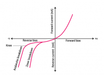
I read jjiasniew's comment earlier today, and it led me to Google Zener diode transfer characteristics earlier today. Among other hits, I found this: https://byjus.com/physics/difference-between-zener-breakdown-and-avalanche-breakdown/This particular difference in zener diode behaviour (probably due to "avalance" vs. "zener") is not very well described.
That page reminded me that not all Zener diodes use the same breakdown mechanism. I wondered if Zener breakdown might produce a softer knee than avalanche breakdown. But the graph in that article (attached to this post) didn't support that idea, so I dismissed it.
So thank you again for your post. Without your input, I still wouldn't have understood that low-voltage Zener diodes have a softer knee.
Same here. I started teaching myself electronics as a child, age still in single digits, and I've read countless electronics books since then, ranging from simple books aimed at hobbyists, to advanced textbooks for engineering students. But I don't think I've ever come across this information. (Or if I did, it was so long ago that I'd completely forgotten it.)At least I could not find any available articles describing this and my old university books did not contain any hints either.
Very interesting, and it opens up some new avenues for experimentation!
-Gnobuddy
Attachments
Yep... I should have looked up the schematic before posting ;-)There is no cold clipper in the 4-input amps. Only the master volume ones have a cold clipper.
See this BZX84 series datasheet for some exemplary curves (page 10; fig. 5, 6, and 7).low-voltage Zener diodes have a softer knee
The best analogue triangle-to-sine shaper I know off (it produces no sharp kinks, and lower THD, than all the typical solutions), is an oddball single-JFET circuit that never seems to have been used in audio function generators. It was, however, used in analogue (audio) synthesizers, where it was used for the same purpose: shaping triangle waveforms into sinewaves.A sine shaper works much better with 2.5 kT/q of emitter degeneration than with a pure tanh.
94 dB would be pretty good - but, sadly, I don't think you can actually get anywhere close to that, because of the troublesome nature of the signal source we're dealing with here.Suppose you don't use a CA3046 but a better pair of matched transistors, say something with about 30 ohm of base resistance and good log conformity at 1 mA of collector current, and you attenuate the signal to 10 mV peak, which is really too small because you then hardly get any distortion. According to my calculation, you then get a 94 dB(A) signal to noise ratio, almost the value of a compact disc with triangular dithering. Doesn't that suffice?
The trouble is that a guitar pickup needs to see a load of at least 1 megohm.
Let's say you have 500 mVpp signal at the pickup (consistent with the sample data from Rod Elliott's website). To get that down to 20mVpp, you have to attenuate by a factor of 25 times.
So we could use a resistive potential divider consisting of a 1 meg resistor, and a 40 k resistor (39 k in practice).
(If you're being very picky, we could use 960k and 40 k and still get 1M impedance and 25 times attenuation. This won't materially change any conclusions we arrive at by considering a more practical 1Meg and 39k).
Since 1M is much bigger than 39k, the Thevenin impedance at the junction of the two resistors is still basically 39 k. This is the source impedance "seen" by the input stage of the guitar amplifier.
(I've also neglected the additional source impedance inside the guitar, which might be considerable. This only adds to the 1M resistor, making the approximation I used even more accurate - Rthevenin is basically 39k.)
So we're now dealing with the thermal noise from a 39k resistor, rather than the 30 ohm one you considered. 🙁
And that is a major problem.
Since thermal noise voltage is proportional to the square root of resistance, that means the noise voltage from a 39k resistor will be about 36 times bigger than what you calculated (for a 30 ohm resistor).
That in turn means the S/N ratio will be about 31 dB worse than you estimated, dropping from 94 dB to only 63 dB.
Not so very long ago, 63 dB was as good as we could hope for in home audio reproduction. A new vinyl LP record might just about manage 63 dB S/N ratio. Cassette decks of the time rarely did better than 40 dB S/N ratio without Dolby, and 50 dB with Dolby B. When Dolby C and Dolby S arrived two decades later, your shiny new cassette deck with Dolby S might just barely have managed 63 dB.
Guitar amps, however, tend to be intolerably hissy at 63 dB S/N ratio. Two factors combine to create this problem: the first is that e-guitars are typically turned up to much higher SPL than home Hi-Fi, and that immediately means you'll hear much louder hissing when the guitar is not playing. S/N ratio might be the same in both cases, but the noise floor is a lot louder in the second case, and it may become objectionably audible.
So, even if 63 dB S/N ratio was adequate when you were listening to music from your Hi-Fi at 85 dB peak SPL, it's unlikely to be adequate with a guitar amp turned up to produce 100 dB SPL.
(100 dB is stupidly high, but unfortunately, very typical, and maybe unavoidable if a loud drummer is part of the band. This sort of stupid-loud playing is why so many guitarists have damaged their hearing.)
With the SPL 15 dB higher, when the guitar is not playing, the hiss from the guitar amp will be 15 dB louder than the hiss from the Hi-Fi. Chances are that's going to be annoyingly loud.
The above discussion applies to guitar amplifiers set for "clean tone", i.e., there's not a whole lot of signal-squashing / overdrive going on.
But if the amplifier is set to intentionally produce lots of overdrive or distortion (the guitarist is playing an Eddie Van Halen cover rather than jazz), then there is a second factor to deal with, and the situation becomes much worse. This second factor is a real humdinger!
The second factor is this: guitar amps set to overdrive heavily will have far more voltage gain than needed for linear reproduction.
(By definition - it's the excess voltage gain that tries to drive the output beyond linear limits, causing the overdrive.)
This "overdrive" is exactly the same thing we've been calling "squashing" in this thread - except that if the guitarist is playing a musical style that involves lots of overdrive or distortion, there will be a lot of this squashing going on.
When the guitar is being played, and the amp is actually being overdriven in this way, the effective voltage gain of the amplifier is reduced by the same "squashing". Output signal voltage is squashed, input voltage isn't, so the ratio of output voltage to input voltage (i.e. the voltage gain) is also reduced.
While this is going on, noise voltage is squashed along with the signal. S/N ratio doesn't suffer too much.
But when the guitar goes silent - with the amp still set to this high gain - there is no longer any squashing, and voltage gain of the amplifier rises to its full value. The guitar isn't putting out any music signal, but thermal noise at the input is now amplified by the full (uncompressed, unsquashed) voltage gain of the amplifier. This makes the thermal hiss much louder.
(I'm assuming the thermal noise voltage itself isn't big enough to overdrive the amplifier. This assumption is true in every case I've encountered.)
As a for-instance, imagine the amplifier was being overdriven enough to produce 20 dB of "squashing" or compression when the guitar is playing. When the guitar goes silent, the voltage gain effectively rises by 20 dB, making the hiss 20 dB louder.
In effect, our former 63 dB of S/N ratio is now reduced to only 43 dB. Combine that with the typically louder SPL from a guitar amp, and that is a lot of hiss to deal with!
This isn't a hypothetical situation - it's very real. Guitarists who play very heavily distorted styles of music (meaning they are using much more than 20 dB of excess gain) are virtually forced to use an FX pedal called a "noise gate" in their signal chain. The noise gate attempts to sense when the guitar signal stops (between notes), and to mute the otherwise intolerable background hiss whenever this happens.
The use of a noise gate is standard practice for all guitarists who play heavily distorted genres of music nowadays. And the amplifiers they're using are not saddled with the additional burden of a heavily attenuated guitar signal at the input - they're getting the full 500 mVpp or whatever the guitar puts out.
There may be a loophole: if you can run a unity-gain buffer, with a very low output impedance, between the guitar and the 25:1 attenuator, you should be able to do much better, and approach closer to the 94 dB you estimated. The buffer sees the full 500 mVpp guitar signal at its input, improving its own S/N ratio, and because it has a low output impedance, the voltage divider at the output can be made with much lower-value resistors (much lower than 1M/39k, that is).
I'm not sure how practical it would be to get all the way down to 30 ohms at the output of the resistive voltage divider. Something like a 27 ohm/680 ohm voltage divider would do that, adding about 26 ohms to the transistor base resistance of 30 ohms you suggested.
From my personal point of view, any possible benefits from the tanh(Vi/(2 Vt)) transfer function of a BJT LTP isn't worth the sacrifice of being forced to attenuate the guitar signal before you can amplify it. Attenuating a signal always worsens the S/N ratio, and doing this deliberately goes against the grain. (Though I must admit the volume pot inside the guitar does exactly this very thing.)
In practical terms, I suspect that the crude S-shaped transfer function created by using two anti-parallel silicon diodes across an op-amp feedback resistor may not be all that different in shape from the tanh() function created by an ideal LTP - and the resulting voltage range is more usable: the diode pair needs something around 1Vpp to traverse the full width of the "S curve", rather than the 20 mV limits of an LTP.
One of these days I should simulate both those solutions in LTSpice and see how different the curves actually look. 🙂
These days blue LEDs are relatively cheap and easy to find, and using a pair of those instead of ordinary small-signal silicon diodes would boost the range of the "S curve" to at least 3 - 4 volts peak to peak, if that was wanted.
Yes indeed. This is basically the solution created by the mysterious Russian engineer who goes by "KMG" on the forums, and used in his remarkably good MOSFET guitar amp designs. I don't know if he created this solution, but I've never seen it used by anyone else.If you have the voltage headroom available, you can connect a string of n diode-connected transistors as emitter degeneration for each transistor, increase the signal level by a factor of n + 1 and improve the signal to noise ratio by 10 dB * log10(n + 1).
Yet another possibility is to make the LTP from a pair of low-transconductance JFETs or MOSFETs, if one can find them. Both JFETs and MOSFETS have been transformed into high-transconductance switching devices in recent years, and it's getting harder to find old-school ones designed for linear amplification.
This wouldn't give you an exact hyperbolic tangent function - it wouldn't be exactly tanh(x). But it would still be some sort of roughly S-shaped curve, with broadly similar characteristics, except for a more useable input voltage range.
-Gnobuddy
Thanks!See this BZX84 series datasheet for some exemplary curves (page 10; fig. 5, 6, and 7).
I'll have to study that for a bit to understand what it means for our purposes. But it looks interesting immediately: the 2.4V device data on page 5 states a 275 ohm differential resistance at 1 mA forward current. And that's about ten times higher than the differential resistance of an ideal silicon diode forward-biased to the same 1 mA.
-Gnobuddy
Of course there should be a buffer between the guitar pick-up and the attenuator. I thought that was too obvious to mention.
It wasn't. I've never learned how to read someone else's mind. 😀Of course there should be a buffer between the guitar pick-up and the attenuator. I thought that was too obvious to mention.
-Gnobuddy
In practical terms, I suspect that the crude S-shaped transfer function created by using two anti-parallel silicon diodes across an op-amp feedback resistor may not be all that different in shape from the tanh() function created by an ideal LTP - and the resulting voltage range is more usable: the diode pair needs something around 1Vpp to traverse the full width of the "S curve", rather than the 20 mV limits of an LTP.
One of these days I should simulate both those solutions in LTSpice and see how different the curves actually look. 🙂
These days blue LEDs are relatively cheap and easy to find, and using a pair of those instead of ordinary small-signal silicon diodes would boost the range of the "S curve" to at least 3 - 4 volts peak to peak, if that was wanted.
Assuming an emission factor of about 1.5, the current through a diode increases by a factor of 10 for a 90 mV voltage increase. If its effect only becomes noticeable at 500 mV ... 2 V depending on what semiconductor material you use and then increases by a factor of ten for every 90 mV extra, you have pretty hard clipping compared to a tanh. In that sense you can better use a Schottky or a germanium diode than a silicon junction diode or even a blue LED.
I woke up this morning and realized I had forgotten to protect the transistors against base-emitter avalanching, see below or the attachment for a corrected schematic. I also added two 220 pF capacitors to limit the bandwidth of the op-amp stage (filter off some ultrasonics), although those are not strictly needed.

Attachments
Hi Gnobuddy, you may want to have a look at LSK389 or 489 for LTP. Ask me how I know 😉Yet another possibility is to make the LTP from a pair of low-transconductance JFETs or MOSFETs, if one can find them
- Home
- Live Sound
- Instruments and Amps
- Discussion: Unwanted clipping in solid-state e-guitar preamps