Yes solid state op-amp based circuitry will need careful consideration when it comes to overdrive, avoiding rail clipping and adding "imperfections" to the preamp response. It would be nice if more designers in the mass market were mindful of this.. I haven't played on a Fahey amp but I am assured that JM is very aware and mindful..he has stated such on many occasions and has been an advocate of DIYers using good quality guitar speakers, and helping others out with SS amplifier builds, mods and repairs in general. There are good solid state designers, though we do see a lot of very well known brand products that don't seem to follow that theory into practice. Maybe the management of those companies don't want their solid state amps to sound as good as their tube amp offerings. What may change that game is the onset of DSP driven amps. Compared a Katana amp to a Frontman series FM212R.. there is a big difference in the overdrive response and overall sound.Yes, if you insist on using op-amps!
But no, if you use SS devices that already have their own built-in imperfections, like JFETs.
These days I think that is a more fruitful route to take, at least for one-off DIY builds - I don't have to worry about mass-production, as you do.
If I may make a comment on this, and not taking anything away from your good suggestion. Consider also not making the LTP or differential pair in perfect symmetry. An offset will be a static wave shaping, moving the break points of the S-curve. If the slopes outside the break points are just slightly different, you have then introduced an imbalance dependant on the signal level. If the LTP overdrives two devices with slightly different gains, and they are driven to saturation, you will have duty cycle modulation. It will generate this more noticeably than bias wiggle or static offset in a preamp. Not going to go into more details at this moment, but hope you find it interesting. Cheers!When using a differential pair (with or without stacked diode-connected transistors in the emitter leads) as soft clipper, it could be useful to have an offset adjustment knob. Put it in the centre and you get pure odd-order distortion, turn it to the left or right and you add even terms as well.
I certainly find it interesting, but I don't quite understand what you mean. Could you make a sketch of the curve that you want?
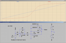
Too busy tonight to type as many words as usual, so I'll let the LTSpice screenshot speak for itself.If it's effect only becomes noticeable at 500 mV ... 2 V....you have pretty hard clipping compared to a tanh. In that sense you can better use a Schottky or a germanium diode than a silicon junction diode or even a blue LED.
Take a look. The transfer function doesn't look like "pretty hard clipping" to me. As I suspected, it doesn't look all that different from a tanh() function, qualitatively speaking. Mathematically speaking, it will not be an exact tanh(), but that doesn't matter at all for our purposes. There's nothing magic about the tanh() function.
The op-amp/ diode clipper circuit also uses far fewer components than a practical BJT LTP circuit. You don't need to divide down the guitar signal, you don't need a constant current source, you don't need the additional headaches of a balanced differential stage to convert the LTP output to a tanh().
(Only the differential output signal - the difference between the two BJT collector voltages - is a tanh(). To convert that differential signal to a single-ended unbalanced signal, you need to follow the LTP with a balanced differential amp stage.)
The simple diode or LED clipper also gives more usable input and output signal levels. Input level is tunable with R2, output level is tunable by choice of diode or LED or zener.
It's quite easy to add additional resistors and diodes to provide additional soft breakpoints in the transfer function. You need one resistor and two diodes for each additional breakpoint (if you're okay with symmetric nonlinearity). I've shown variations of that circuit before.
To save time, I grabbed and placed generic LEDs and op-amps that are built into LTSpice. There's nothing special about either of them. I didn't bother to Google to find out what colour that particular LED puts out; my guess is white or blue, but it's not really that important for the purposes of this discussion.
Note that the input signal is a linear ramp. Not a sine wave. The linear ramp makes it easy to see the nonlinearity in the transfer function.
I set the ramp to rise linearly from -2V to +2V over 15 mS. I picked the +/- 2V values to make it easy to compare the linear input ramp with the tanh-like output voltage, which happens to have about the same peak-to-peak amplitude using these particular LEDs.
The first op-amp is in the circuit only to invert and scale the input voltage, compensating for the inversion in the diode clipper stage. This lets us compare a rising linear ramp input with the rising tanh-like output voltage. (Otherwise you'd be comparing a rising input with a falling output, making it a little harder to visualize exactly what's going on.)
If I had more time I'd model a BJT LTP as well, and scale and plot its differential output voltage on the same graph, for direct comparison with the op-amp diode clipper. Even without this, though, we can see quite clearly that the diode clipper transfer function is a pretty similar S-curve to the tanh() function from the LTP.
For use in a guitar amp, I'm not a fan of the crude diode clipper, and I'm even less a fan of the way-too-sensitive BJT LTP. To me, both sound monotonous (lacking in duty cycle modulation), crude (too much THD), and prone to rather abrupt and harsh overdrive (not progressive and gradual enough).
Still, to give the devil its due, this type of tanh-like transfer function is less harsh, and less abrupt, than an op-amp output slamming into its supply rails. Even a not-very-good LTP or diode clipper is definitely an improvement over that worse-case scenario of a hard-clipping op-amp.
Less-bad than the worst possible case - I think that's what the British used to call "Damning with faint praise"! 😀
Gotta run!
-Gnobuddy
Attachments
Microprocessors have become very powerful, and very cheap, in just the last few years. Five years ago we were using an 8-bit chip running at 16 MHz and requiring a $70 hardware programmer to teach one of our electronics courses. Last year the Raspberry Pi Pico came out - 32 bit, dual core, running at up to 133 mHz, no hardware programmer needed, and it costs five bucks!What may change that game is the onset of DSP driven amps.
DSP hardware has gone through the same evolution, so it's only a matter of time before a DSP guitar preamp costs less than an analogue one full of diodes and resistors and fiddly bits.
The Flamma FS06 Preamp I like so much went on sale (in the USA) for $60 at Walmart this Christmas - incredible quality to price ratio.
I have a Katana 50. It's the first solid-state e-guitar amp I've ever found usable. I used it earlier today.Compared a Katana amp to a Frontman series FM212R.. there is a big difference in the overdrive response and overall sound.
I once briefly owned a near-cousin to the FM 212R for about five minutes; I couldn't stand the harsh clean tones and the even worse overdrive, so I ripped out the electronics, and transplanted the guts of my Fender Superchamp XD (which has a tube power amplifier section) into the cab, to take advantage of the larger speaker.
-Gnobuddy
In the case of the LTP you proposed, you could change one of the collector resistors (either R 3 or R4) to a trimmer pot , or try using unmatched Q1A Q1B transistors.. the idea is to slightly unbalance the response of the S curve so it's not in perfect symmetry. The slope/curve of one half will be a bit "off". In the case of Gnobuddy's example of diode pair across the 100 K resistor NFB on inverting op amp, One of the diodes could be connected at a tap along the 100K instead of right across. Say split to 20K and 80 K in series have one diode across both resistors, and the opposing diode connected one leg in between the 20K and 80 K. That may be extreme, but in the case of push pull output tubes, you may get a matched pair that will bias the quiescent current fairly evenly, but the transconductance and gain response can be different. Even if you have NFB back to an LTP, it may try to cancel the error out, but when the amp output is clipping the NFB won't be able to cancel out the extreme signal excursions.I certainly find it interesting, but I don't quite understand what you mean. Could you make a sketch of the curve that you want?
Because of the exponential voltage-to-current characteristic of a bipolar transistor, an m:1 scaling in a differential pair has the same effect as an offset of ln(m) kT/q. Scaling the collector resistors will just cause a DC offset at the output of the second op-amp, you still get a tanh.
What could help is to stack a different number of transistors left and right. I'll draw a modified schematic.
What could help is to stack a different number of transistors left and right. I'll draw a modified schematic.
Yes I agree in this configuration of BJT that would manage to do it.What could help is to stack a different number of transistors left and right. I'll draw a modified schematic.
Too busy tonight to type as many words as usual, so I'll let the LTSpice screenshot speak for itself.
Take a look. The transfer function doesn't look like "pretty hard clipping" to me. As I suspected, it doesn't look all that different from a tanh() function, qualitatively speaking. Mathematically speaking, it will not be an exact tanh(), but that doesn't matter at all for our purposes. There's nothing magic about the tanh() function.
I took a LED that I once recovered from a damaged bicycle light I found on the street, presumably while walking through Delft. It turned out to be a bright red LED. I also took a 9 V battery, some crocodile clip wires, a bunch of resistors and a cheap TDM600 digital multimeter, which has a 1 Mohm input resistance when measuring DC voltages. With this set-up and correcting for the current through the meter, I measured the LED forward voltage for currents from 732 nA to 1 mA and got this result for the forward current in A versus the forward voltage in V (dark blue curve):
It fits nicely with the red exponential curve, which is 25 uA at 1.65 V with a decade/93 mV slope (emission factor about 1.6).
Using two resistors to make a voltage divider and using the meter's 200 mV range as a 200 nA range (as 200 mV/1 Mohm = 200 nA), I measured the LED's reverse current to be 0.3 nA at 1.52 V and 0.5 nA at 2.05 V. These measurements are quite inaccurate, but good enough to show that reverse current is negligible.
Using the IF = 25 uA * 10(VF - 1.65 V)/0.093 V model, I then calculated the current versus voltage characteristic of a LED with 100 kohm in parallel with it. As the reverse current is negligible, the result with two antiparallel LEDs will be the same for positive excursions and the same shape, but mirrored in the origin for negative excursions. The result is:
Essentially a straight line up to 1.5 V, and a rather sharp corner above that, not even close to a tanh.
There you are.Yes I agree in this configuration of BJT that would manage to do it.
Attachments

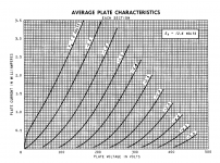
Before we all go too far down the road of creating increasingly complex BJTs together, to create increasingly complex circuits that have rather tightly curved nonlinear transfer functions, I thought that it might be helpful to remind ourselves what the transfer function of the most commonly used preamp tube actually looks like.
The attached image is taken from the datasheet for a 12AX7, and shows the curves for one of the two vacuum triodes it contains.
Note how very subtle the curvature is. This is what we need to reproduce if we want a solid state guitar amplifier to be capable of sounds similar to a valve one.
Tightly curved transfer functions shift abruptly from "too clean" to "too dirty", and that's the problem with all these BJT-based circuits. Everything we can do with diodes iand BJTs s hamstrung by the fact that diodes have such a sharp curvature to their transfer function.
-Gnobuddy
Attachments
Did you look at the graph from my LTSpice simulation of the op-amp with LED clamping diodes? Where is the straight line and the sharp corner(s) you're predicting?Essentially a straight line up to 1.5 V, and a rather sharp corner above that, not even close to a tanh.
Of course LEDs have an exponential transfer function. You didn't need to measure that, we know it from basic semiconductor theory of PN junctions. It's decades-old information. Nothing new there.
In an LTP, one BJT gradually robs current from the second as its VBE increases with rising signal voltage. The current that's "robbed" rises exponentially.
In the diode clipper, one diode gradually robs current from the parallel resistor as the voltage across it increases with rising signal voltage. The current that's "robbed" rises exponentially.
The end result is much the same in both cases.
Look at the output voltage graph from the LTSpice simulation. It does look very much like a tanh() function.
As far as I can see, your analysis is failing because you left out a crucial component: the op-amps feedback resistor, which is in parallel with the clipping diodes.
This is the same mistake as forgetting to include a constant current source in the "tail" of the LTP, and instead putting a constant voltage source there. If you do that, you'll get the straight line and sharp kinks you're expecting from the BJT pair, too. (Can't really call it a "long tailed pair" if the "long tail" has been replaced by a voltage source.)
I'm still very busy today. If I do find the time, I'll add the LTP simulation to the other one, so we can compare them directly. But it's already quite obvious that the output from the op-amp/diode clipper is not a straight line with sharp corners, as you're predicting. Just take a look at the screenshot of the LTSpice simulation.
-Gnobuddy
You should walk around the block 😉curious why no one has used low voltage zeners anode to anode in series for the diode clipper?
Lots of examples and even quite more sophisticated configurations, such as the Fender mix-and-match diode types (Zener+silicon+LED), Crate dynamic varying symmetry, different-knee arrays, etc.
Fortunately, sighing is still free, even after rampant inflation over the last three years. 😀Sigh...
Gotta run!
-Gnobuddy
Could you actually READ the damn post before replying to it?As far as I can see, your analysis is failing because you left out a crucial component: the op-amps feedback resistor, which is in parallel with the clipping diodes.
This is the same mistake as forgetting to include a constant current source in the "tail" of the LTP, and instead putting a constant voltage source there. If you do that, you'll get the straight line and sharp kinks you're expecting from the BJT pair, too. (Can't really call it a "long tailed pair" if the "long tail" has been replaced by a voltage source.)
I'm still very busy today. If I do find the time, I'll add the LTP simulation to the other one, so we can compare them directly. But it's already quite obvious that the output from the op-amp/diode clipper is not a straight line with sharp corners, as you're predicting. Just take a look at the screenshot of the LTSpice simulation.
-Gnobuddy
I read yours, saw a simulation plot that seems to defy all logic and all basic semiconductor physics and got curious: would the LED have an enormous emission factor, Zenering at a quite low voltage, some other gross non-ideality or would it just be wrongly modelled, like components used far outside their intended operating range often are? (Model parameters for an LED meant to be used at a current of about 20 mA could very well be generated by curve fitting over some small current range around 20 mA, giving unphysical results elsewhere.) Hence the measurements, using whatever LED I had at hand, and the calculation of the response of a parallel LED-resistor circuit.
Last edited:
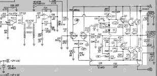
It was done successfully by Randall in the 90's. Pantera's Walk sound, probably the most controlled agressive drive, feels like a sharp cuting sword ...How about using N-channel JFET common-source stages? JFETs behave qualitatively similar to triodes: smoothly curved characteristics from gate-source voltage to drain current, gate conduction when the gate voltage goes too high, soft clipping when the drain-source voltage gets too small.
I cloned all sort of tube drives until 2011 for a friend which is now one of the best guitar player in my country, probably amongst the first 10 : mesa dual rectifier, peavey c30, vox ac30, marshall...all except a few sacred monsters from the 60's, huges and kettner which has a little bit higher gain than mesa, all tubes, even some op amp based marshalls...only Soldano compares to Randall in terms of control and timing but different sound.You can't say it's worse, just very different.
Attachments

Last edited:
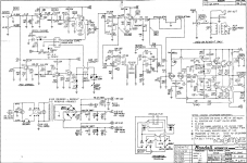
Traynor also in the mid to late 80s with their Bloc 50 and 100G, which we discussed has JFET and also JFET-BJT stages. It has a very good clean channel, not clinical or harsh at all. There is a sheen/glisten/shimmer to its sound, not unlike a Fender Twin, and it does this much better (IMHO) than say a Fender FM212R clean channel..It was done successfully by Randall in the 90's.
The Bloc distortion channel is similar but with another JFET-BJT pair using back to back diodes clipper in the local NFB, its ''okay'' but not spectacular. Not much adjustability or progressive distortion with that. I am working on an alternative ''distortion channel'' of sorts, FET based but more progressive distortion not relying on opposing diodes as ''clippers'', but perhaps using some diode based soft limiting on FET stages as I`ve described previously. Just 3 stages is about enough to get into overdriven JTM 45 and even Super Lead territory. It won't do modern metal sounds but that isn't my playing goal or listening preference anyways.
- Home
- Live Sound
- Instruments and Amps
- Discussion: Unwanted clipping in solid-state e-guitar preamps