Marcel isn't the only one here who knows high-level electronics theory...pretty sure there are several of us here.Without Marcel there's no real discussion on highly theoretical aspects...
Personally, I don't post mathematical equations because they scare many people off. I work out the math myself, then I try to explain it in words so that everyone can understand, even if they don't know calculus or semiconductor physics.
Yes, and more importantly, it was rude of me. My sincere apologies to Marcel. I lost it for a moment, and I was rude. I'm sorry.using expressions like "knock yourself out" with him is unproductive.
-Gnobuddy
When you talk with somebody here, spy his clock on Earth to see how tired he is.There's at least 7...11 hrs difference between Belgium and Canada...There's a good probability that a math teacher is equally tired to a lumberjack at 10PM .
And I am scared less by death than mathematics, but I'm on an electronics forum not an embroidery one...so I can't expect seeing colourfull flowers on t-shirts.
And I am scared less by death than mathematics, but I'm on an electronics forum not an embroidery one...so I can't expect seeing colourfull flowers on t-shirts.
Last edited:
Since they are being fed by a current source, apply Kirchoff's current law, and you get nonlinear equations to solve. The voltage across the diode is the logarithm of the current through it (with the usual scaling factors you know about).Suppose you have two types of diodes with equal emission factors, but very different forward voltages at a given current. Both follow IF = Is (exp(VF/(nkT/q) - 1), but with very different values of Is.
Two of the same type in antiparallel with a resistor across them will then conduct a current
I = Is (10V/Vdec + 10-V/Vdec) + V/R
I don't usually post equations because I'm not sure how many people on the forum are actually helped by seeing them. However, in this case, it's the only way to communicate what I'm thinking.
In the attached image of a quick scribble from my notepad, to find the voltage across the diodes, you have to substitute i from equation (2) into equation (1), and then solve equation (1). (Trying to type equations into this forum is too tedious for me.)
Equation (1) is a nonlinear equation. Note that both the diode voltage, and the diode current, are both embedded in it. and off the top of my head, I can't think of a way to solve it analytically.
However, it can be solved numerically because we know the (exponential) relationship between Vd and Id.
LTSpice does exactly this, and does it very well.
I think it's a red herring to assume that (some? all? many?) of the diode models in LTSpice are defective. All diodes follow the Shockley equation (exponential) over several orders of magnitude of current. Plotted properly, on a log-lin graph (plot the log of the current), all diode characteristics are simply straight lines over many orders of magnitude of current.
You could say diode curves do not really have a "knee". The "knee" is simply an artifact of the way our limited human brains work - we don't understand exponentials, and our brains think linearly, not exponentially.
Another way to think about this: an exponential (exp(x)) is a self-similar curve. Zoom in, or zoom out, by any amount, and the curve always has exactly the same shape. There isn't one "knee" - it's the same shape however much you zoom in, or out.
-Gnobuddy
Attachments
Half the posts on this board are basically colourful flowers on T-shirts...colourful lit-up triode valves mounted on polished wooden bases, colourful loudspeaker drivers mounted on ridiculous flat baffles, even colourful solid-state audio circuits built into 3D pretty pictures using stiff copper wire interconnections and no PCB or substrate! 😀I'm on an electronics forum not an embroidery one...so I can't expect seeing colourfull flowers on t-shirts.
There is a rule-of-thumb when publishing a book addressed to a lay audience: every equation in the book will cost you half your potential buyers. One equation will make half of your buyers decide not to buy the book. Two equations will make 75% of your potential buyers decide not to buy the book. And so on.
I began to teach myself electronics at a very young age, in elementary school, when I had very limited math skills. So I figured out how to understand many simple circuits in words, without math, as that was the only way to explain them to myself.
Later in life, I did learn the math and the science. But when I became a teacher, most of my (junior college level) students were very weak at math, and I went back to explaining circuits in words, pictures, and analogies to them. They understood much better that way.
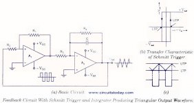
For example, there is a common type of oscillator that uses a Schmitt trigger connected to an integrator. It produces square and triangle waves. See the attached image.
I can explain the operation of that circuit to you very simply, without math: imagine a squirrel on a see-saw. The squirrel follows the algorithm "Always run uphill".
So the squirrel runs uphill until her weight tips down that end of the see-saw, then she turns around and runs the other way, until the other end of the see-saw drops, and so on, forever...
The height of the squirrel, plotted against time, is the triangle-wave.
The height of either see-saw end, plotted against time, is the square wave output.
Isn't that much easier to understand than I = C dV/dt, and therefore V = 1/C (time integral of V)? 😀
Of course there's a point at which the concept is too complex for words and pictures, and only equations will do. We don't usually reach that point on these forums, though.
-Gnobuddy
Attachments
I don't buy anything at the moment, some people aren't selling anything either or get paid for teaching the planet ...
Seeing as we are discussing math and transfer functions, there are some shared points with the DSP approach and solid state.
Early DSP (ie Line 6, Digitech and similar products) were a bit limited in modeling tube transfer functions because of speed and processing power. Probably
also took a while until designers got a handle on things and the processors got more capable. Maybe they originally had one or two wave shapers handling preamp and power amp duties.
Now they can do multiple wave shaper functions, emulating the function of a whole amp response, quite convincingly. I have played on an Axe Fx, have heard Kemper and played on earlier types of Line 6 and Digitech. The newer generations are much more convincing, but also at some times sound somewhat static and flat, but that depends on how good the coding is..I don't think it's hardware that is limiting anymore.
So the original transfer function for a single triode (preamp) waveshaper would have broken down into 3 formulae which would approximate the tube transfer function.
For more information on this transfer curve and associated functions:
https://www.ampbooks.com/mobile/dsp/preamp/
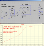
Nowadays, they can get a much closer approximation using 6 or more formulae, basically a series of 3rd or 4th order polynomial equations that represent partial sections of the full transfer curve at specific breakpoints. You`re only running one polynomial equation for any given input value 'x'. So the coding would have conditions for x and then based on the result (where the x value lies in the range of signal input), calculate y output using one of the polynomials.
The transfer curve is not far off from the S-curve we have been discussing here. This can be implemented in solid state, similar to the S-curve but different slopes and shifting away from the origin. What I don't know is if there is or has been any DSP coding done for dynamic bias shifting, but that would involve something like a peak envelope detector (an absolute value of x and scale factor, time averaged) and applying that result to an offset shift of signal input x, decaying over a period of time. Again seems to be a ''straightforward'' thing to do in solid state.
To me , a key to progressive low order harmonic distortion is the idea of using multiple wave shapers, and consideration of dynamic bias shift and appropriate filtering. As in solid state, the DSP code (and converters) need to stay within the upper/lower limits, without over-range errors which cause conversion distortion (the worst!).
Early DSP (ie Line 6, Digitech and similar products) were a bit limited in modeling tube transfer functions because of speed and processing power. Probably
also took a while until designers got a handle on things and the processors got more capable. Maybe they originally had one or two wave shapers handling preamp and power amp duties.
Now they can do multiple wave shaper functions, emulating the function of a whole amp response, quite convincingly. I have played on an Axe Fx, have heard Kemper and played on earlier types of Line 6 and Digitech. The newer generations are much more convincing, but also at some times sound somewhat static and flat, but that depends on how good the coding is..I don't think it's hardware that is limiting anymore.
So the original transfer function for a single triode (preamp) waveshaper would have broken down into 3 formulae which would approximate the tube transfer function.
For more information on this transfer curve and associated functions:
https://www.ampbooks.com/mobile/dsp/preamp/
Nowadays, they can get a much closer approximation using 6 or more formulae, basically a series of 3rd or 4th order polynomial equations that represent partial sections of the full transfer curve at specific breakpoints. You`re only running one polynomial equation for any given input value 'x'. So the coding would have conditions for x and then based on the result (where the x value lies in the range of signal input), calculate y output using one of the polynomials.
The transfer curve is not far off from the S-curve we have been discussing here. This can be implemented in solid state, similar to the S-curve but different slopes and shifting away from the origin. What I don't know is if there is or has been any DSP coding done for dynamic bias shifting, but that would involve something like a peak envelope detector (an absolute value of x and scale factor, time averaged) and applying that result to an offset shift of signal input x, decaying over a period of time. Again seems to be a ''straightforward'' thing to do in solid state.
To me , a key to progressive low order harmonic distortion is the idea of using multiple wave shapers, and consideration of dynamic bias shift and appropriate filtering. As in solid state, the DSP code (and converters) need to stay within the upper/lower limits, without over-range errors which cause conversion distortion (the worst!).
I'm rather surprised at just how crude the early Line 6 modelling (referenced in that link) was. No wonder their stuff sounded so bad!
Line 6 promised a dozen glorious vintage tube amps in a box, but what you actually got was a dozen different types of kazoo in a box.
I was naive enough to fall for the advertising, and the widespread applause on Internet forums, three times. I wasted a lot of money, and a lot of time, trying to get any kind of sound I liked out of any of these horrible products.
Fool me once, shame on you. Fool me twice, shame on me. Fool me three times? I must be a right royal idiot.
Agreed. Even the simple op-amp diode clipper circuit can do this. Plunk down, say, an LED in one direction, a silicon diode in the other. Add a resistor in series with one of them to alter the transfer function slope when that diode conducts. Et voila, asymmetric S-curve transfer function.The transfer curve is not far off from the S-curve we have been discussing here. This can be implemented in solid state, similar to the S-curve but different slopes and shifting away from the origin.
Which, unfortunately, tends to produce the same crude buzzing kazoo sounds as the early Line 6 products. 🙁
I can hear duty cycle modulation from the little Flamma Preamp. Whether this was achieved by simulated dynamic bias shifting, or the DSP code implements the same effect in some other way, I don't know.What I don't know is if there is or has been any DSP coding done for dynamic bias shifting
One way to do that is to square the individual signal sample values (you'd have to subtract the mean, the DC bias value at the input of the A/D converter). That would give you a string of positive numbers, each the square of the instantaneous signal voltage. Then average several of the squared samples together, and you have the mean square value for the signal. Shift out samples and repeat...that would involve something like a peak envelope detector (an absolute value of x and scale factor, time averaged)
Maybe just tweak the coefficients of the appropriate polynomial dynamically? I think that would do the trick, too...and applying that result to an offset shift of signal input x, decaying over a period of time.
Back in the mid 1980s, John Murphy figured out one way to do this using an op-amp, a couple of diodes, and a capacitor. His circuit is also an op-amp/diode clipper, but the output duty cycle doesn't stay frozen - it shifts with signal level. Murphy used his patented circuit block in many early Carvin guitar amplifiers he designed.Again seems to be a ''straightforward'' thing to do in solid state.
I think I still have a few schematics of those old Carvin amps saved on my home PC. I'll see if I can find one of them when I get home tonight.
To me, Murphy's circuit, while better than the typical diode clipper, is still lacking compared to a good tube guitar amp in overdrive. The smooth progression from "valvey" clean tone to rich distortion is lacking. Clean tones are still sterile (too clean), and even the overdrive has a sort of clinical quality to it. It's not rich and lush like a good tube guitar amp.
I think so, too.To me , a key to progressive low order harmonic distortion is the idea of using multiple wave shapers, and consideration of dynamic bias shift and appropriate filtering.
I haven't had the opportunity to play through high-end pioneer digital amp modellers (Kemper, AxeFX, etc). But I listen to videos showcasing these and similar products on Anderton's Music You Tube channel, among others.
A lot of the time, some of the very expensive modellers sound very realistic to me. Unfortunately, this isn't always the case. A Fender Tonemaster digital amp will set you back over $1000 CAD (twice that in some cases), and in online tests, every now and then you can hear the carefully crafted simulated sound fall completely apart, and for a split second, it sounds like a cheap and nasty analogue solid stage practice amp.
Anderton's Music has videos of many relatively affordable (not as eye-wateringly expensive as AxeFX, etc) digital amps, and digital multiFX pedals (all of which include amp modelling now). Some of these have brand names that are relatively unfamiliar (Valeton, Hotone, Nux, etc).
It's interesting to listen to these. Every single one is far, far, far better than the early Line 6 crap. But none of the affordable ones grabbed my ears to the point where I thought "I want to shell out the Canadian equivalent of 300 British pounds for one of those!".
For me, the little Flamma FS06 Preamp is still bang-for-the-buck champion, by far. It has no built in FX pedals, all it does is emulate seven different tube amps, with a clean and dirty channel for each. The FS06 lives on my pedalboard now.
This was one thing that impressed me about the Fender Mustang Micro. It runs on a single internal lithium cell (4.2V at full charge), meaning the internal DSP probably runs at the now-common 3.3V DC.the DSP code (and converters) need to stay within the upper/lower limits, without over-range errors which cause conversion distortion (the worst!).
In spite of the low supply voltage, I can't hear any audible harshness from it (set to clean tone) with any of my guitars played in a reasonable way. Neither the analogue input buffer, nor the A/D converter, overloads in any audible way. Props to Fender for getting that right!
(The amp models are nowhere near as good as the ones in the Flamma FS06, though, even though the Mustang Micro costs considerably more.)
-Gnobuddy
Last edited:

Yes, and more importantly, it was rude of me. My sincere apologies to Marcel. I lost it for a moment, and I was rude. I'm sorry.
-Gnobuddy
I haven't been particularly polite to you either recently, so my apologies to you as well.
I appreciate that. Thank you.I haven't been particularly polite to you either recently, so my apologies to you as well.
-Gnobuddy
Here's one way to reproduce an asymmetrical transfer function (like the early Line 6 one referenced in Shanx' link), using a simple diode clipper. Just add one more resistor, in series with one of the two diodes.
Imagine that. You can build a nasty-sounding guitar amp using DSP, or much more simply, using an op-amp and a couple of diodes.
Unless, of course, you happen to love the sound of a kazoo, in which case the amp will sound lovely to your ears.
Warning: watching this video might permanently damage your sanity and lower your IQ:
-Gnobuddy
Attachments
Last edited:
How do you know that? Have you tried it? If you did your opinion cannot be trusted anymore ...Warning: watching this video might permanently damage your sanity and lower your IQ:
-Gnobuddy
By the way, i've read it would be recommended to have a series resistor with every diode cause op-amps aren't really that good at driving 30...60 ohms dynamic impedances.
I watched about 5 seconds, and I could feel my sanity slipping away and my IQ dropping...How do you know that? Have you tried it?
Another minute, and I might have sold my apartment and bought an NFT with the money. 🙄
If you don't know what an NFT is, it is a JPEG that some people pay millions of dollars to "own" - even though they could right-click the mouse and download the same JPEG to their PC for free.
Today's crooks and confidence men don't sell you bridges or Arizona beachfront property. Today they sell you Bitcoin and NFTs.
That is quite true if you wire the diodes in parallel with the output of an op-amp (like the Proco Rat approach). You need a resistor in series to limit maximum current, and to be kind to the op-amp.By the way, i've read it would be recommended to have a series resistor with every diode cause op-amps aren't really that good at driving 30...60 ohms dynamic impedances.
However, in the type of diode clipper shown in my post above, the output current of the op-amp is set by the input current and input resistor - not by the load on the output! In fact, the output current will not change, whether you put 1 ohm, 10 ohms, or 1000 ohms in series with it. **
So it's quite safe to use "naked" diodes with no series resistances in this particular circuit. Both the diodes and the op-amp will be safe and happy.
** within limits, of course. It works as long as the output doesn't clip.
-Gnobuddy
Since they are being fed by a current source, apply Kirchoff's current law, and you get nonlinear equations to solve. The voltage across the diode is the logarithm of the current through it (with the usual scaling factors you know about).
I don't usually post equations because I'm not sure how many people on the forum are actually helped by seeing them. However, in this case, it's the only way to communicate what I'm thinking.
I did try to explain to you in words why diodes with a large forward voltage lead to rather abrupt clipping unless their emission factor is unusually high, see post #158, https://www.diyaudio.com/community/...id-state-e-guitar-preamps.391513/post-7221294 I then tried it by measurements combined with numerical calculations (posts #170 https://www.diyaudio.com/community/...id-state-e-guitar-preamps.391513/post-7223393 and #184, https://www.diyaudio.com/community/...id-state-e-guitar-preamps.391513/post-7224324 ). After all that, I resorted to equations.
In the attached image of a quick scribble from my notepad, to find the voltage across the diodes, you have to substitute i from equation (2) into equation (1), and then solve equation (1). (Trying to type equations into this forum is too tedious for me.)
Equation (1) is a nonlinear equation. Note that both the diode voltage, and the diode current, are both embedded in it. and off the top of my head, I can't think of a way to solve it analytically.
However, it can be solved numerically because we know the (exponential) relationship between Vd and Id.
LTSpice does exactly this, and does it very well.
The voltage as a function of the current is probably a transcendental equation that has no analytical solution, but fortunately, if you just want to get an idea of the shape of the function (or compare the shapes for circuits with different diode types), you can as well calculate the current as a function of the voltage and swap the x and y variables.
I think it's a red herring to assume that (some? all? many?) of the diode models in LTSpice are defective. All diodes follow the Shockley equation (exponential) over several orders of magnitude of current. Plotted properly, on a log-lin graph (plot the log of the current), all diode characteristics are simply straight lines over many orders of magnitude of current.
If it does so with an unrealistically large emission factor, it is still a poor model (or actually a poor model parameter set). I strongly suspect that the LED model you used has a very high emission factor, far greater than the LEDs I measured.
I have worked with various types of circuit simulators since 1988 (I've simulated things almost every working day over the last three decades) and you always have to be aware of the possibility of poor modelling, particularly when you use components outside the range of operating conditions that whoever made the model expected.
You could say diode curves do not really have a "knee". The "knee" is simply an artifact of the way our limited human brains work - we don't understand exponentials, and our brains think linearly, not exponentially.
Another way to think about this: an exponential (exp(x)) is a self-similar curve. Zoom in, or zoom out, by any amount, and the curve always has exactly the same shape. There isn't one "knee" - it's the same shape however much you zoom in, or out.
-Gnobuddy
That's precisely what I calculated in post #199, https://www.diyaudio.com/community/...id-state-e-guitar-preamps.391513/post-7224759 . You can in theory always get the same curve no matter what the forward voltage at a given current is, but the shunt resistance that you need quickly gets out of hand (increases exponentially) if the emission factor is of the order of what I measured for my LEDs.
The 1N914 you used for your simulation in post #186, https://www.diyaudio.com/community/...id-state-e-guitar-preamps.391513/post-7224355 , is a pretty good choice, at least the ones from OnSemi are. Looking at figure 3 of their datasheet, their emission factor is almost 2 and their forward voltage pretty low. Using the same type of calculation as for my LEDs, I get this curve for the parallel connection of a 1N914 and 3.9 kohm:
Comparing it to 0.56 tanh(7200 I):
The tanh looks different, but I can't possibly say it looks better. At first it deviates more from a straight line than the 1N914 diode clipper, but then it clips harder.
Last edited:
That's why I suggested that @Gnobuddy try LTSpice's QTLP690C LED model in my last post. The NSCW100 model has an emission coefficient of 9.626, while the QTLP690C's is 1.5.the shunt resistance that you need quickly gets out of hand (increases exponentially) if the emission factor is of the order of what I measured for my LEDs.
A comparative test using the same resistor values.
Edit:
Here are the model statements, found in LTSpice's standard.dio:
Edit:
Here are the model statements, found in LTSpice's standard.dio:
.model QTLP690C D(Is=1e-22 Rs=6 N=1.5 Cjo=50p Xti=100 Iave=160m Vpk=5 mfg=Fairchild type=LED)
.model NSCW100 D(Is=16.88n Rs=8.163 N=9.626 Cjo=42p Xti=200 Iave=30m Vpk=5 mfg=Nichia type=LED)
Attachments

Last edited:
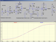
Attached are some plots of a triode emulator circuit I've been playing with compared to an accurate 12AX7 model. It's fully discrete and uses only BJTs and diodes to create the nonlinearities. First plot is the anode characteristics (Va=0V-500V; Vg1=-5V-0V, 0.5V step; Rs=1mΩ). Second and third are the transfer characteristics (Va=50V-350V, 50V step; Rs=33k).
Do you use translinear circuits? More generally, does anyone use translinear circuits for guitar amplifiers? You can make just about any non-linear function involving rational powers with translinear circuits (power of 3/2, for example, as in Child's law). The dynamic range is not great, but can be > 90 dB(A) when you do your best.
No, the circuit in question is effectively a nonlinear voltage controlled current source with feedback. Diodes are the main nonlinear elements, though one of the BJTs contributes a bit as well. Noise is not amazingly low at around 16nV/sqrt(Hz) EIN, but is probably good enough.Do you use translinear circuits?
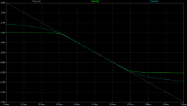
LTSpice thinks the QTLP690C produces sharper corners to the transfer function (screenshot attached).
Not a particularly good approximation to a tanh(), as Marcel has been saying.
But I don't want to lose sight of the forest for the trees. IMO, getting too focused on the exact shape of these curves takes away our attention from a much more important point: We already know that neither the LTP nor the diode clipper sounds good in a solid-state guitar amplifier.
This is why I said earlier that this is a wild-goose chase. Circuits like these have been used for decades, in literally thousands of different products. Some use Ge diodes, some Si diodes, some LEDs, some mixtures of different types of diodes. Some are set up to clip symmetrically, some asymmetrically.
All of them sound less-bad than letting a TL072 output clip against the supply rails. But, in spite of all the variations, none of them sound good by themselves. None of them sound like a tube amp, either.
By itself, these diode clipper effects pedals (also used in many solid-state guitar amps too) sound nasty.
If you feed the output of a diode-clipper into a good tube amp, and add reverb and delay to smooth out the harsh sound, the resulting sound can be very musically usable.
I can't help but think that this rather like the recipe for making tofu curry taste like beef curry: throw 5 grams of tofu into a large pot full of beef curry. 🙂
To me, the tube-like curves bmc0 posted are considerably more interesting than any sort of diode clipper. If signal levels and impedances of bcm0's circuits are in the right range, and the circuit block needed to create that curve is not too complex, those curves look very interesting. (Remember we need to simulate 4 - 5 tube stages feeding each other in cascade to replicate the behaviour of real tube guitar amplifiers.)
Gotta run!
-Gnobuddy
Attachments
The input sensitivity is the same as a typical 12AX7 stage. Input impedance is high and it has accurate 'grid' current when driven to clipping. The bad news is that Ra is 1/10th of a 12AX7 and the voltage gain is very limited (about 2 rather than about 60 for a 12AX7), so it definitely can't be used as a 'drop-in' replacement to emulate every stage of a tube preamp.If signal levels and impedances of bcm0's circuits are in the right range, and the circuit block needed to create that curve is not too complex, those curves look very interesting.
My goal with that circuit was to see if I could design a fairly accurate triode-like input stage using BJTs and diodes that works with ±15V supplies.
- Home
- Live Sound
- Instruments and Amps
- Discussion: Unwanted clipping in solid-state e-guitar preamps