Depends of what you intend to use if for. A CLC would help for HF noise. The transformer's secondary resistance should help with that. But I wouldn't bother for the audio range.
I want to use it for Vas and LTP pair for amplifier
Interesting. The PM829 arrangement does have better tempco than just a simple Zener. But not quite as good as a LM329.
An even better tempco seems to be a LM329 + 6.2V Zener in the PM829 arrangement.
I put all versions in the attached photo. A bit harder to follow but you can see the LM329+6.2V Zener has a better tempco by far vs all the other arrangements.
I will try it with the BJT versions as well, but should work out the same I presume.
Attachments
Even more interesting is that it seems that you could do the same with LEDs. Tempco is better and you also raise Vref voltage to 6V with two red LEDs, vs the around 3.5V with them normally connected in series. This can also be retrofitted to the existing boards I made, you just rotate the top LED.
Attachments
Last edited:
What do you mean better than MPSAx6? In what way?
You can use either LM329, either Zener, either the PM829 arrangement mentioned by kimschips, either a LM329+zener in PM829 arrangement, either two LEDs in PM829 arrangement (LED829?)
You can use either LM329, either Zener, either the PM829 arrangement mentioned by kimschips, either a LM329+zener in PM829 arrangement, either two LEDs in PM829 arrangement (LED829?)
I think RickRay tried using ZTXx51 pair for the dienoiser with a LM317 and had issues with stability. Those should be lower noise.
I measured the noise of this supply at around 800pV/sqrtHz (between 10kHz and 20kHz). It's already way overkill for audio. PSRR measured around 150dB, which again, is way overkill. You won't notice any difference even if some lower noise transistors are used.
I think I have a ZTX851 and I'll test it in a denoiser configuration with this latest supply, also using two LEDs in PM829 configuration. Curious of the results, will post them. I don't have any ZTX951 so I can't test the dienoiser.
If I'm having stability issues I won't spend too much time testing the ZTX transistor, the performance is good enough with the MPSAx6 pair.
I did try other BJTs with the versions that use a BJT as pass transistor, and the MPSAx6 pair gave the best PSRR performance. So I recommend using that.
Trileru
Could you also simulate 12v output from post 11, using to 6V8 zeners coupled in series like Walt young PM829?
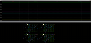
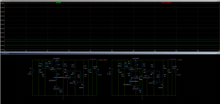
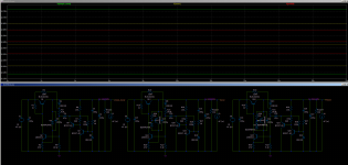
I tried for the positive feedback circuit with the BJT pass transistor.
Attached photos:
1. simple LED block vs GLED block vs GLED(829?) block.
As can be seen the 829 arrangement in the GLED block offers really good tempco with just LEDs.
2. same thing but with Zeners. Again, the PM829 arrangement inside the GLED block offers really good tempco.
3. comparison between PM829 and PM829 inside GLED.
4. comparison between LED829 inside GLED and PM829 inside GLED. (Mr. Jung sorry for butchering your circuit names).
Attachments
Last edited:
I think RickRay tried using ZTXx51 pair for the dienoiser with a LM317 and had issues with stability. Those should be lower noise.
I measured the noise of this supply at around 800pV/sqrtHz (between 10kHz and 20kHz). It's already way overkill for audio. PSRR measured around 150dB, which again, is way overkill. You won't notice any difference even if some lower noise transistors are used.
I think I have a ZTX851 and I'll test it in a denoiser configuration with this latest supply, also using two LEDs in PM829 configuration. Curious of the results, will post them. I don't have any ZTX951 so I can't test the dienoiser.
If I'm having stability issues I won't spend too much time testing the ZTX transistor, the performance is good enough with the MPSAx6 pair.
I did try other BJTs with the versions that use a BJT as pass transistor, and the MPSAx6 pair gave the best PSRR performance. So I recommend using that.
First of all thanx a lot for all your efforts here.
2nd i get the voltages I want now, very nice.
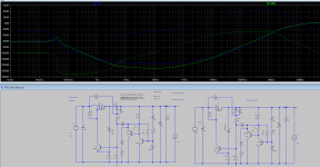
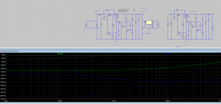
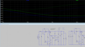
I meant better transistors to produce lower noise. Anyway are my curves in my simulation ok? I mean at 10KHz seems to go up, I am not sure how much dbs are achievable.
At 2MHz you still have about 20dB of PSRR. But add your secondary resistance to the voltage source in the sim. The HF PSRR will be higher in reality.
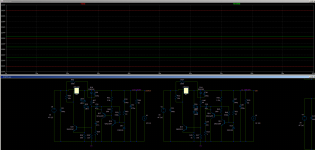
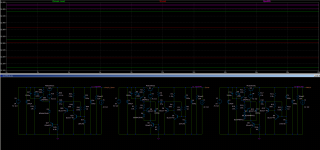
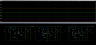
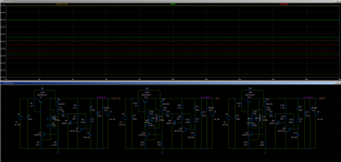
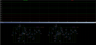
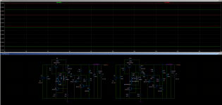
I ran the simulations for the negative feedback circuit. The same trend is noticed but the GLED block does not help to the extent it does in the positive feedback circuit.
Photos are in the same order as the previous post.
Photos are in the same order as the previous post.
Attachments
At 2MHz you still have about 20dB of PSRR. But add your secondary resistance to the voltage source in the sim. The HF PSRR will be higher in reality.
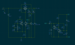
I added a CLC in front, because it does great work in my high power rails, I mean I have built it and it really helps. It adds a very interesting feature, seems to reduce noise in high frequency, If I read this correctly . I also added an LM317 in the end to be able to adjust voltage.
I will also add the AC transformer and rect diodes in front to get a full simulation.
Attachments
But you can adjust the voltage from the two resistors that the denoiser connects to. You don't need the LM317. Plus that ruins the low noise output of the discrete regulator. Remove the LM317.
Install a 20k pot instead of those resistors. Check my boards to see how I did it.
Install a 20k pot instead of those resistors. Check my boards to see how I did it.
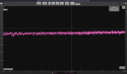
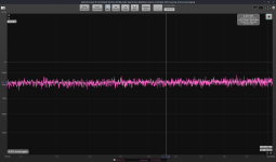
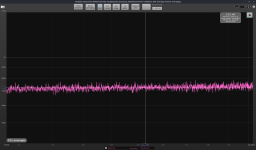
I measured the MOSFET version with the GLED block for Vref, with two red LEDs.
I measured denoiser with ZTX851, denoiser with MPSA06 and dienoiser with ZTX851 and MPSA56.
My calibration value changed as I discovered a software gain control that was offset from some time ago, and I reset it and recalibrated the value in both ARTA and REW. Previous values remained the same, PSRR of the MOSFET supply and also the LNA noise. Just wanted to explain why my calibration value is different now in the screenshots.
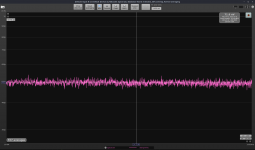
Shorted LNA measured 495pV/sqrtHz. Subtracting from the measurements the noise comes out like this:
Denoiser with MPSA06 - 750pV/sqrtHz
Dienoiser with ZTX851/MPSA56 - 650pV/sqrtHz
Denoiser with ZTX851 - 530pV/sqrtHz
Denoiser PSRR is the same with either MPSA06 or ZTX851.
So if you're looking for the lowest noise the denoiser with ZTX851 seems like the way to go, but you have "only" around 130dB of PSRR with just the denoiser.
Attached photos are the measurements in the presented order, and the last picture is my shorted LNA input.
12.2Vout with 150R load.
I measured denoiser with ZTX851, denoiser with MPSA06 and dienoiser with ZTX851 and MPSA56.
My calibration value changed as I discovered a software gain control that was offset from some time ago, and I reset it and recalibrated the value in both ARTA and REW. Previous values remained the same, PSRR of the MOSFET supply and also the LNA noise. Just wanted to explain why my calibration value is different now in the screenshots.
Shorted LNA measured 495pV/sqrtHz. Subtracting from the measurements the noise comes out like this:
Denoiser with MPSA06 - 750pV/sqrtHz
Dienoiser with ZTX851/MPSA56 - 650pV/sqrtHz
Denoiser with ZTX851 - 530pV/sqrtHz
Denoiser PSRR is the same with either MPSA06 or ZTX851.
So if you're looking for the lowest noise the denoiser with ZTX851 seems like the way to go, but you have "only" around 130dB of PSRR with just the denoiser.
Attached photos are the measurements in the presented order, and the last picture is my shorted LNA input.
12.2Vout with 150R load.
Attachments
Trileru
Could you also simulate 12v output from post 11, using to 6V8 zeners coupled in series like Walt young PM829?
I found a dual 6.2V Zener diode in SOT23 package, with common cathode. Part number DZ23C6V2.
Also I think this works for both positive and negative output without any change.
I tried for the positive feedback circuit with the BJT pass transistor.
Attached photos:
1. simple LED block vs GLED block vs GLED(829?) block.
As can be seen the 829 arrangement in the GLED block offers really good tempco with just LEDs.
2. same thing but with Zeners. Again, the PM829 arrangement inside the GLED block offers really good tempco.
3. comparison between PM829 and PM829 inside GLED.
4. comparison between LED829 inside GLED and PM829 inside GLED. (Mr. Jung sorry for butchering your circuit names).
Are you sure that there Are enought current from Q7 to PM829 circuit? Walt j uses about 8mA?
Thanks again.
Are you sure that there Are enought current from Q7 to PM829 circuit? Walt j uses about 8mA?
Thanks again.
Depends on the Zeners used I think. You can tweak the current from the 220R resistor. I have two 6.2V THT Zeners and I might test tempco when I get some time. But since these supplies are used for the analog part of audio I don't think tempco is really that important, as long as it's not horrible.
Is the performance I see on the simulation true? Seems exotic. What exactly are the resistors i can change to change voltage? Are they more than one?
You can use a 20K pot instead of R24/R25. If Vref is around half of the output voltage the two resistors would have a similar value.
Attachments

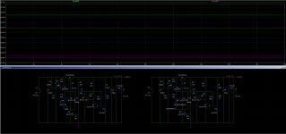
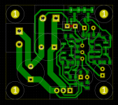
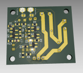
I updated the MOSFET pcb design to include the GLED block for better tempco, also added the option for two 0805 LEDs and also a SOT23 Zener footprint for either a single Zener setup, either the PM829 setup with two Zeners (part number DZ23C6V2 should work in this position).
If you wish to omit the GLED block then don't install Q2 and install a 0R resistor instead of R9.
If you install the LEDs then omit D6. If you want a simple Zener in SOT23 package then you need to install a 0R resistor instead of D2 (and omit D3).
If the PM829 block works the same for positive and negative voltage output then you just need to rotate the other polarized parts on the pcb for negative voltage output (and swap all transistors with their complementary). If the PM829 diodes have to be rotated for negative voltage output then there's SOT23 packages with the diodes rotated inside (common anode).
Attachments
- Home
- Amplifiers
- Power Supplies
- Discrete regulators with denoiser