Where have you ordered the boards from?
I live in Denmark but do not know about shipping cost.
Thx
Kim
I live in Denmark but do not know about shipping cost.
Thx
Kim
JLCPCB. Take a look at their low volume sales prices. You may find you can get 5 for less than $20 with shipping if you stay with the default options for finish etc. I figured these were prototypes and can get better quality if needed after testing these out.
I've ordered a number of boards from JLCPCB and have been extremely satisfied with both the boards and the fast production and shipping times, around two weeks normally, order placed to your doorstep.
I got a pair of MJE15032/MJE15033 made by On, from Farnell.
Measured the positive voltage output versions for both circuits again. The first circuit with the MJE15032 measured the same PSRR so my first MJE15032 that I tried with is legit. About 152dB PSRR.
The second circuit I measured this time with MJE15033 and PSRR went up to a bit over 150dB. This is a bit more than LTSpice predicted (about 147dB).
I used the MPSA06/MPSA56 pair for the denoiser circuit.
edit: when I find the time I'll measure the negative version for the first circuit now that I have the MJE15033.
Last edited:
What about sound quality have you compaired to super regulator?
Best regards
I have used it in an application yet. And I never used the SR. Maybe someone who builds it can share their impressions.
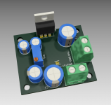
I made a version for the second circuit for higher current output. I used a IRF9520 P-channel MOSFET instead of the BJT pass transistor. This has the advantage of the base current being low. Vref bypass cap is not needed in this configuration. If you bypass the startup diode with 100uF (6.3V rating is enough) then you get about 10dB extra PSRR. Also a compensation network for the denoiser circuit is required, 47nF+1R seems to work fine.
I measured this setup with 12.2Vout, 150R load (about 100mA total) and 8R load (1.5A). Denoiser BJTs were MPSAx6. Lower small signal BJT was MPSA06 but 2N5551 should work fine in this spot.
As Vref I used a simple 6.2V Zener diode without the transistor. But simulation shows two LEDs should work fine and I recommend the transistor as it helps with tempco in the case of LEDs.
For output cap I used a Panasonic FR 470uF/25V, which has a very low ESR, about 40mOhm. I'm not sure if such a low ESR is needed, I didn't test other caps. Seems to work fine with this one.
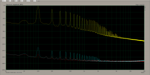
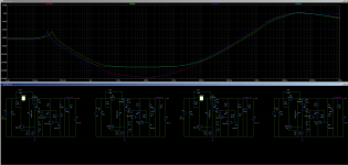
PSRR results for 150R load:
denoiser - 130dB
dienoiser - 150dB
Noise was around 0.8nV/sqrtHz (I subtracted my LNA noise from the measured figure) between 10kHz-20kHz.
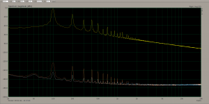
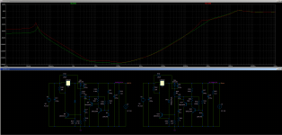
PSRR results for 8R load:
denoiser - 122dB
dienoiser - 143dB
Noise was the same. Denoiser noise is a touch lower but has a worse profile, goes up between 10kHz and 20kHz. Might be either due to the Zener I used as Vref (as opposed to LEDs on the previous measurements), either due to the MOSFET used as pass transistor.
I suppose the output current is limited by the pass transistor you use. This arrangement should be more efficient as well as the base current for the pass transistor is low.
For the negative output version of this circuit you could use a IRFZ44N, and the lower power transistor should be 2N5401 for best PSRR performance.
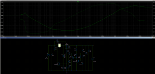
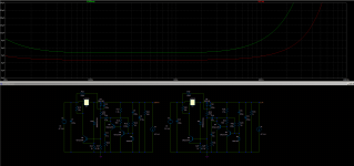
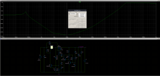
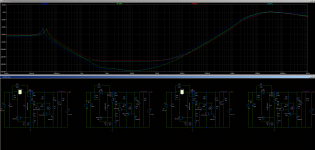
1st picture is PSRR for 150R load, 2nd picture is PSRR for 8R load (input ripple/denoiser/dienoiser).
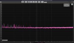
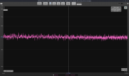
3rd picture is the noise of the dienoiser with 8R load, 4th picture my LNA input shorted.
5th picture is the circuit I used in this measurement.
IRF9520 spice model can be found here:
IRF9520, SiHF9520 Power MOSFET | Vishay
It seems to be in stock in most places and has a good price, cheaper than MJE15033.
edit: to get a high measurement dynamic range I used 220uF input cap for 150R load and 3420uF (2200uF+1000uF+220uF) for 8R load. This puts the input ripple around 0dBV in both cases.
2nd edit: last picture is sim result for output impedance for 100mA and 1.5A output.
3rd edit: I will update the pcb design to allow for higher input capacitance, remove the Vref cap and also keepout the soldermask from the main power traces so you could fill them with solder for lower resistance.
I measured this setup with 12.2Vout, 150R load (about 100mA total) and 8R load (1.5A). Denoiser BJTs were MPSAx6. Lower small signal BJT was MPSA06 but 2N5551 should work fine in this spot.
As Vref I used a simple 6.2V Zener diode without the transistor. But simulation shows two LEDs should work fine and I recommend the transistor as it helps with tempco in the case of LEDs.
For output cap I used a Panasonic FR 470uF/25V, which has a very low ESR, about 40mOhm. I'm not sure if such a low ESR is needed, I didn't test other caps. Seems to work fine with this one.
PSRR results for 150R load:
denoiser - 130dB
dienoiser - 150dB
Noise was around 0.8nV/sqrtHz (I subtracted my LNA noise from the measured figure) between 10kHz-20kHz.
PSRR results for 8R load:
denoiser - 122dB
dienoiser - 143dB
Noise was the same. Denoiser noise is a touch lower but has a worse profile, goes up between 10kHz and 20kHz. Might be either due to the Zener I used as Vref (as opposed to LEDs on the previous measurements), either due to the MOSFET used as pass transistor.
I suppose the output current is limited by the pass transistor you use. This arrangement should be more efficient as well as the base current for the pass transistor is low.
For the negative output version of this circuit you could use a IRFZ44N, and the lower power transistor should be 2N5401 for best PSRR performance.
1st picture is PSRR for 150R load, 2nd picture is PSRR for 8R load (input ripple/denoiser/dienoiser).
3rd picture is the noise of the dienoiser with 8R load, 4th picture my LNA input shorted.
5th picture is the circuit I used in this measurement.
IRF9520 spice model can be found here:
IRF9520, SiHF9520 Power MOSFET | Vishay
It seems to be in stock in most places and has a good price, cheaper than MJE15033.
edit: to get a high measurement dynamic range I used 220uF input cap for 150R load and 3420uF (2200uF+1000uF+220uF) for 8R load. This puts the input ripple around 0dBV in both cases.
2nd edit: last picture is sim result for output impedance for 100mA and 1.5A output.
3rd edit: I will update the pcb design to allow for higher input capacitance, remove the Vref cap and also keepout the soldermask from the main power traces so you could fill them with solder for lower resistance.
Attachments
-
 150R_PSRR.png84.8 KB · Views: 474
 -
 8R_PSRR.png83.8 KB · Views: 419
 -
 N_8R_nfb_dienoiser.png136.6 KB · Views: 417
 -
 LNA_shorted.png147.8 KB · Views: 418
 -
 Screenshot from 2021-04-02 19-14-17.png114.4 KB · Views: 438
 -
Draft48(1).asc9.5 KB · Views: 119
-
 Screenshot from 2021-04-02 19-25-03.png94 KB · Views: 187
Last edited:
Also forgot to mention, from simulation it seems that with 100mAout there needs to be at least 0.3Vdrop across the pass transistor to get the highest PSRR performance.
For 1.5Aout around 1.6Vdrop minimum gives the highest PSRR performance.
edit: Also Vout difference between 150R and 8R load was around 10-20mV I think, so regulation is good enough.
For 1.5Aout around 1.6Vdrop minimum gives the highest PSRR performance.
edit: Also Vout difference between 150R and 8R load was around 10-20mV I think, so regulation is good enough.
Last edited:
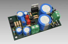
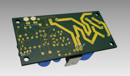
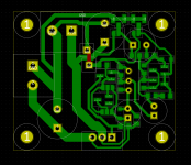
I made an update to the pcb, now has two 18mm input capacitors. Should be fine for 1.5Aout. You could push it further if you can cram enough capacitance to account for min Vdrop across the pass transistor.
Vref transistor (if used) should be something like BC327. The lower transistor has 2N5551/MPSA06 footprint. Denoiser circuit BJTs have footprints for MPSAx6.
I kept the soldermask off the main traces so you can fill them with solder for higher current output.
The limiting factor is the bridge diodes. If you want an even higher current version you'd have to tell me what is your desired footprint for a bridge.
This version can also be diyed. Kicad project, pdf for diy and gerber files included in the zip file.
Size is around 74mm x 37mm.
edit: this pcb design is not tested, so you make it at your own risk!
Attachments
Last edited:
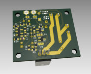
Since the rectifying block limits the current output (apart from the MOSFET) I decided to design a board that accepts rectified DC input only. This way you can have the rectifying part on a separate PCB with all the needed bells and whistles. Maybe this is useful for anyone.
Board size is 43mm x 37mm. It can be configured for both positive voltage output and negative voltage output. The only part that can't be rotated is the Zener diode, and there's two smd jumpers to configure for positive or negative voltage output.
This board uses SOT23 footprint for the Zener diode, can easily be found in different voltage flavors.
BJTs are all SOT23, you can find this package for MPSA06/MPSA56 and 2N5551/2N5401.
1N4148 diodes have SOD323 footprint.
Electrolytic capacitor footprints should allow for higher voltage output. You can add a 10mm diameter one for the input capacitor.
SMD passives are all 0805.
This pcb design has not been tested so you make it at your own risk.
edit: this board is diyable. you'd need to put a link instead of the red trace. gerbers are for both sides so for fab house version you don't need to do anything.
you can either install a 20k pot or use the resistor footprints to set your output voltage (R1/R2).
Attachments
Last edited:
Playing with the sim file it seems that IRF9Z24N has good performance at high current output, and it's the cheapest I could find at Mouser. Under 1$ a piece, and should offer about 153dB of PSRR at 6Aout.
Min Vdrop across the MOSFET for max performance seems to be around 3V at 6Aout. That means around 18W dissipated by the MOSFET.
IRF9Z24N is a 55V max part.
Min Vdrop across the MOSFET for max performance seems to be around 3V at 6Aout. That means around 18W dissipated by the MOSFET.
IRF9Z24N is a 55V max part.
Attachments
Made a small revision to the last design, moved the output cap. I also made a BOM from Mouser. Total cost without 0805 passives comes out at around 6.5$ out of which the potentiometer is almost 1/4 of the total cost.
Attachments
Last edited:
Hi Trileru, I need help for a design for +(20 to 25V) and -(50 to 60V) adjustable lowest noise possible upto 0.5A, no need to be cheap. I have the simulation files (unfortunately minus doesn't work) and it is easy for me to create PCB.
Can I upload on this thread?
Can I upload on this thread?
Maybe something like this? When choosing the Zener voltage shoot for around half the output voltage.
You could use IRF9Z24N for +25Vout but for +60Vout you should use something like IRF9530.
For the negative rail there's not much performance difference between various common MOSFETs. A IRF510 seems to work fine.
You could use IRF9Z24N for +25Vout but for +60Vout you should use something like IRF9530.
For the negative rail there's not much performance difference between various common MOSFETs. A IRF510 seems to work fine.
Attachments
Actually I forgot to adjust the current through the Zener. Try this version.
edit: also for the higher voltage output versions, the 6.8k denoiser resistor drops almost the whole output voltage across it, so make that a 0.6W resistor if possible, maybe even 1W rating.
edit: also for the higher voltage output versions, the 6.8k denoiser resistor drops almost the whole output voltage across it, so make that a 0.6W resistor if possible, maybe even 1W rating.
Attachments
Last edited:

Depends of what you intend to use if for. A CLC would help for HF noise. The transformer's secondary resistance should help with that. But I wouldn't bother for the audio range.
- Home
- Amplifiers
- Power Supplies
- Discrete regulators with denoiser