I recommend these pcb to be used to a max of 1.5A. And I'll have to release a set of values I'd recommend for this current output. I think it could be done for up to 30Vout, but I first need to check some things.
For the up to 4A output needs I don't recommend this pcb design. Some part footprints or even layout would have to be different, different bridge rectifier for the 4A of current.
For the 4A current output, also for a PC, I'd go with LM338+dienoiser. I thought about doing a pcb design for the full current output of the LM338 but that's something I didn't yet look into.
Also you have to keep in mind that replacing the SMPS with a linear regulator you'd have a good bit of efficiency loss. Also even if you put a clean supply for the PC, it usually has different buck/boost converters on its pcb, for the different rails that are usually needed.
So using a clean linear regulator as the main supply might solve some noise, but you'd still have some sources for HF noise in it.
Yes, I am aware of that, that for pointing it out. 😉
Do you have a schematic/PCB for LM338+dienoiser?
Thanks 🙂
Could you please do a dual +/- 1.5A board? I have some headphone amps that would make great use of this board.
+1 for this, an all in one rectified PSU would be nice, maybe the CM circuit for HPA's?

Bipolar-PSU-all-in-one-with-rectifiers opens up a can of worms.
Yes/no: support transformers with dual independent secondaries?
Yes/no: support center tapped transformers?
Yes/no: support single secondary transformers (AC wall warts)?
Yes/no: provide footprints for snubber components across the transformer secondaries?
Yes/no: provide footprints for individual diodes (allows builder to use UltraFast rectifiers)? Or for 4-diode bridge rectifiers? Or both?
How much peak-to-trough ripple can you accept, when drawing 1.5A from both plus and minus rails? (this spec determines the total amount of reservoir capacitors needed after the rectifiers)
Do you want the PCB mounting holes to be electrically connected to the chassis? Or do you want them floating and insulated from the chassis?
For choosing which circuit to build is this an accurate summary?
- For lowest noise build the negative version of circuit #2. (Possibly two copies for +/- with a dual transformer.)
- For the greatest PSRR build the positive version of circuit #1. (Possibly two copies for +/- with a dual transformer.)
- For lowest Vdrop also build circuit #2.
The dual version I did for LM3x7+dienoiser has the option to use a single secondary transformer for both rails, in which case you'd use TO220 diodes. You can also use it with a center tapped transformer with normal diodes.
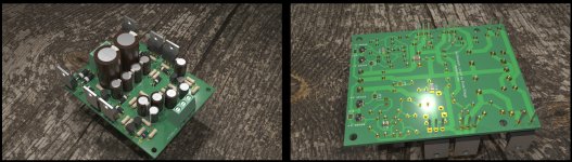
I attached a photo of it, and the latest version for it can be found here:
D-Noizator: a magic active noise canceller to retrofit & upgrade any 317-based V.Reg.
For dual secondary transformers I suggest you use the same supply with output connections inverted for the negative version, or maybe you do two negative versions with inverted connections on the positive.
I have to order both the MJE15032/MJE15033 and ZTX small BJTs for denoiser circuit, as I suspect my MJE15032 has some issues, it underperforms in both circuits where the other transistors measure more or less like the simulation.
If you want more PSRR then the capacitance multiplier versions can help with that. For lowest noise I think any would do as they should be similar with the ZTX in the denoiser circuit. With BC337/BC327 seems the negative versions have lower noise.
I think I'd use the first circuit as it's a bit uncommon with the positive feedback. The positive version simulates a bit better PSRR than I measured, but as I said might be due to the MJE15032 I have. Also for higher voltages it should be really close to -160dB for PSRR.
I used LEDs as Vref in my measurements, but for higher Vout you should use Zener as Vref.
Any suggestions are welcomed for the dual board. Including heatsink type/preference as I usually make them so that you mount the heatsink on the sides of the PCB for cm transistor/regulator transistor/to220 diodes. Or slapping all to220 to the bottom of a metal case.
But adding heatsinks on the PCB itself is going to enlarge the board.
I may also add a current limiting option circuit which might provide some safety in case of something shorting on the output.
With the capacitance multiplier a single 18mm filter capacitor should be enough. I tested the LM317N with capacitance multiplier at 1.25Aout and I think a 3600uF/3900uF should be enough for 1.5A. Or maybe two 16mm footprints for each rail.
I still have to validate the single output pcb designs as I only tested them at 100mA or so. They should be able to push 1-1.5Aout but there's some limitation for higher voltages. I think I simulated a working setup for max 30Vout.
Second circuit has room for a larger resistor that can take up some heat from the base current of the regulator transistor. The first circuit doesn't have it but it can also get one to share some of the heat.
Attachments
For choosing which circuit to build is this an accurate summary?
Any other factors we should consider for choosing which version to build?
- For lowest noise build the negative version of circuit #2. (Possibly two copies for +/- with a dual transformer.)
- For the greatest PSRR build the positive version of circuit #1. (Possibly two copies for +/- with a dual transformer.)
- For lowest Vdrop also build circuit #2.
1. depends, with the ZTX pair for the dienoiser circuit it doesn't matter, all simulate in the 0.63nV/sqrtHz area. For the BC327/337 pair then the first circuit negative version (measured around 0.9nV/sqrtHz) with MJE15033 simulates 12.4dB higher for PSRR at 100Hz. But I'll have to first measure this.
2. yes, but again I'd have to validate the total PSRR with another MJE15032. It failed -5dB short of simulation, but did so for the second circuit negative output version, same 5dB short of simulation, and I want to test with a new transistor again.
3. yes
I will build both (dual pcbs) and try them in a practical application, I'm curious if I'd notice any differences. I think maybe a headphone amplifier, but this will happen at a later point, I don't think I have time for that now.
Last edited:
I won’t mind mounting all the TO-220 devices on the bottom plate. Actually i found this is always cooler than mounting on any specific TO-220 heatsink.
An all-in-one PSU would be fantastic. To save space, a bridge rectifier is good too. Not the same design but amb’s Sigma22 offers some excellent insights for layout.
An all-in-one PSU would be fantastic. To save space, a bridge rectifier is good too. Not the same design but amb’s Sigma22 offers some excellent insights for layout.
Im half asleep but do you have a model for 2SC4793/2SA1837? toshiba discontinued them in TO220pf but brought them back in TO126PF as TTA006B and TTC011
I didnt know if you ruled them out before, but those are nice high Ft low miller transistors
I didnt know if you ruled them out before, but those are nice high Ft low miller transistors
I won’t mind mounting all the TO-220 devices on the bottom plate. Actually i found this is always cooler than mounting on any specific TO-220 heatsink.
An all-in-one PSU would be fantastic. To save space, a bridge rectifier is good too. Not the same design but amb’s Sigma22 offers some excellent insights for layout.
I put the TO220 diode as with a single secondary transformer it would see double the current. Do you think it would be worth it to add another TO220 (edit: per rail) for use with center tapped transformer?
The MUR820 have a 0.9Vdrop or so, at 1A that's already almost 1W. I think they would be stressed at 1A with them stacked like in the Sigma22, but also take up too much space/also asking people to use 4 TO220 diodes with a center tapped transformer. Maybe I could put footprints for both types.
edit: also transformer or bridge snubbers?
Last edited:
Im half asleep but do you have a model for 2SC4793/2SA1837? toshiba discontinued them in TO220pf but brought them back in TO126PF as TTA006B and TTC011
I didnt know if you ruled them out before, but those are nice high Ft low miller transistors
I found models here: ltwiki.org/index.php?title=Standard.bjt
They seem to measure a bit worse than MJE1503x for PSRR, but still good.
Hi,
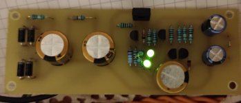
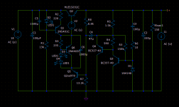
I made one of your suggested circuits. You made if for 30V and I adapted to 40Vout.
I can tell you it is working stable. I ran my phono with it and it sounds great.
Can you review it and tell your opinion? It isn't the newest version, but I had to start somewhere 😉
Regards
I made one of your suggested circuits. You made if for 30V and I adapted to 40Vout.
I can tell you it is working stable. I ran my phono with it and it sounds great.
Can you review it and tell your opinion? It isn't the newest version, but I had to start somewhere 😉
Regards
Attachments
Time for edit has passed 😀
One thing I forgot to mention. In this schematic with LEDs, startup time is about 15 sec, I didn't measure it, but it takes some time for regulator to 'start up'.
Regards
One thing I forgot to mention. In this schematic with LEDs, startup time is about 15 sec, I didn't measure it, but it takes some time for regulator to 'start up'.
Regards
That looks good, congratulations!
Yeah I forgot to mention that these supplies are all slow-start.
One thing to mention is that I wouldn't use LEDs for such a high voltage. I mean looks like you could, but at this point I'd use a Zener to up Vref. Maybe 15V zener.
Also maybe lower R17 to around 6.8k and R15 to 680k. You'd have almost 6mA for the denoiser current. With 10k you have 3.9mA or so. You could also parallel Q11 C-E with a 1200uF cap for more performance.
Let me simulate your conditions and see if there's other improvement in values. R14 might be too high and you risk your supply not starting up also.
Please simulate, but I think that you are wasting a lot of mA in heat only 🙂 my goal was to have stable supply with minimum current consumption.
I am waiting for your reply.
Will try positive feedback version too, I have PCB on my table.
Regards
Edit:
With R11 8K2 LTSpice shows good results, but PSU doesn't start. Maybe if I lower R14 and go up with R11 to 8K2 it would work? With R11 3K and R14 1Meg it starts OK!
I am waiting for your reply.
Will try positive feedback version too, I have PCB on my table.
Regards
Edit:
With R11 8K2 LTSpice shows good results, but PSU doesn't start. Maybe if I lower R14 and go up with R11 to 8K2 it would work? With R11 3K and R14 1Meg it starts OK!
Last edited:
I think R14 value depends on R12, R12 is lowish as you use LEDs which makes for a low Vref, so in turn R13 ratio to R12 is high. If you use a Zener for Vref and increase R12 then 1Meg might be too high. I'd use a 330K for R14 just to be sure the supply starts.
Also 15s seems like a lot. I usually see the LEDs light up in 5 seconds max.
Also 15s seems like a lot. I usually see the LEDs light up in 5 seconds max.
It is for sure about 15sec for LEDs to turn on, but this is not a problem for me.
When you have time, try to simulate with my values.
Regards
When you have time, try to simulate with my values.
Regards
I don't have green LEDs sim models. What Vdrop do they have?
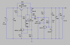
Also for the positive feedback version when you make the PCB there's an important node that needs a clean ground, it's the GND point of R1 in the attached photo. I lost some dB in PSRR at first iterations because that grounding point was not optimal. Check my designs to see how I did it.
edit: Q5 should be BC560 max gain version.
Attachments
Vdrop is 2V for green LEDs.
Thanks for advice for positive version, but I want to test more on this version for now. I'll 'install' 1000uF 16V bypass cap you suggested, anything else?
Regards
Thanks for advice for positive version, but I want to test more on this version for now. I'll 'install' 1000uF 16V bypass cap you suggested, anything else?
Regards
You can also bypass D4 from your schematic with a 330uF cap. Should bring a bit extra PSRR, not much. This cap sees only the 0.6V or so across it.
The 1000-1500uF cap across Q11 sees Vref+Vbe of Q11 so around 4.7V, so a 6.3V-10V rated cap can be used.
The 1000-1500uF cap across Q11 sees Vref+Vbe of Q11 so around 4.7V, so a 6.3V-10V rated cap can be used.
- Home
- Amplifiers
- Power Supplies
- Discrete regulators with denoiser