I was curious how it sounded as a DAC. How does 'decent' sound to you?
Oh, you don’t want to know that 😀. I find weird that in a place where people are obsessing about -140dB close-in phase noise and 10pS jitter (and claiming clear sound improvements when upgrading from common clock generators) you come up with an example of intermodulation issues, when using a sub mediocre chip.
Have you had the chance in this case to correlate the subjective loss of dynamics with any dynamic range or IMD measurements? Myself, I would not be able to separate any dynamics loss in the presence of 1% distortions @16W and 10% @20W, but then I am a recognized stone deaf guy, who listens to music through instruments and computer screens.
@syn08
You have absolutely nothing to thank me for...and I'm not the kind person here as i understood this is not the Kind forum, i just let others excel in kindness...
You have absolutely nothing to thank me for...and I'm not the kind person here as i understood this is not the Kind forum, i just let others excel in kindness...
Thank you again very much for your kind and selfless contributions to this forum. Keep up the good work, please, we all dearly need them.
Everywhere people seems to be in a bad mood these days. Exactly when there starts to shine light at the end of the tunnel (Covid).
Could we please be somewhat nicer? The OP is not as expressive as can be in English but it is not his mother language and he clearly says he has trouble with English.
Could we please be somewhat nicer? The OP is not as expressive as can be in English but it is not his mother language and he clearly says he has trouble with English.
Everywhere people seems to be in a bad mood these days. Exactly when there starts to shine light at the end of the tunnel (Covid).
It is not about Covid, but because their characters. If someone has better idea, better design, claim better in listening skill, usually several people became jealous and mad 😀
I think it has to do with covid as I notice it here in traffic, shops, challenging behavior by youth etc. It seems to have lasted too long for most.
But the ultimate question: how does it sound?
(Best would be a listening test against the following common I/V converters:
- a conventional "zero input impedance" inverting NE5534A, OPA627, OPA2134, OP275, pick your favorite
- a 10R I/V resistor, followed by a tube gain stage
- a transformer (combined with an I/V resistor on the primary or on the secondary)
- a common base transistor stage
- an AD844 I/V)
As for many of us specifications are for the eye, sound is for the ears.
But the ultimate question: how does it sound?
As for many of us specifications are for the eye, sound is for the ears.
Sound perception can be different, because people have different hearing threshold and different listening skill.
If you think the specification is for the eye only, you do not understand the relationship of measurement and the sound perception.
May be for you, the right question is can you hear the sound different of the I/V converter that you mention BLINDLY?
It is not about Covid, but because their characters. If someone has better idea, better design, claim better in listening skill, usually several people became jealous and mad 😀
Really? So people are mad with Doug Self, Elliot or Linkwitz(RIP), haven't seen that.
If anyone presents a new idea in the proper way, with a white paper or page like those pdf mentioned in this thread, it is appreciated and a fruitful discussion can happen.
If you insult others you create an unpleasant atmosphere, you can reach maybe a few people but it will be more difficult to share a good idea.
@bansuri you were the first to be called stupid by your conational in this topic...on the first page after you asked him the best question...strange...
https://www.diyaudio.com/forums/digital-line-level/373375-discrete-converter.html#post6686562
some people really are mad with D Self...not liking his work too much after his long discourse on ne5534.
In my view the printscreens provided in this topic look irrelevant for audio but, if they are true , they might be very interesting for some scientific measuring equipment development.
Last edited:
Interesting images and useful to look at.The output of PCM1794
Graph 3 is visible best.
Peaks with amplitude 1ma and time 2ns.
And this should be integrated accurately.
This overloads each integral audio operating amplifier.
However I'm highly suspicious for two reasons:
1) The output impedance of your I/V is in series with the current from the Dac, causing a larger voltage excursion.
2) To measure 2nsec spikes you have to connect your gear in a very controlled way.
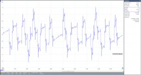
In the first image below you see the recording from the same PCM17xx Dac after I/V, connected from Out+ with coax to 50 Ohm HP461A input, in combination with my scope having a rise time of 12.5 nsec.
The I-V converter is shown in the second image, being the Bel Canto 3.5 Dac.
The 10R is probably inserted in series with the cap for stability reasons.
The 100R out+ going to the HP's 50R input, in combination with the HP's 100x gain results in a gain of 33. for which the vertical scale was corrected.
Signal used was dithered silence.
Closer inspection shows nothing in the low nsec.
The large 1.6mV excursions would suggest 1.6mA peaks, but because of the 10R in series with the 1.5nF cap this reduces to 160uA, still without taking Zout of the LT1468 into account.
So it is probably even below 100uA.
Conclusion is that our images don't match.
Hans
.
Attachments
Sandy,
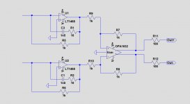
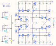
Out of curiousity I simmed your I-V converter from posting #85, see first image.
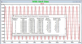
Then I offered a 1Khz current as from the PCM179x, being +/-4mA on top of a 6mA bias, see second image,
With 0.097%THD, the converter felt unhappy, so I reduced the output voltage by replacing 1K by 500R.
THD went down to 0.000 296, but still far from your specs.
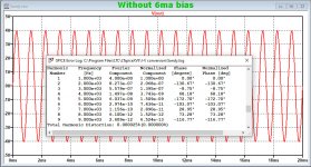
When removing the 6mA bias but keeping the +/-4mA, distortion went down to 0.000 025%, see third image.
Using the +/-2mA from your posting #85, I finally got your 0.000 006%.
So it seems that the presented figures are from simulations with perfectly matched transistors and without bias.
Real life figures are always higher.
There was no difference in THD between 1Khz and 10Khz, which is good.
But it seems that you still have to fiddle a bit on the circuit diagram to cope with bias currents.
Hans
.
Out of curiousity I simmed your I-V converter from posting #85, see first image.
Then I offered a 1Khz current as from the PCM179x, being +/-4mA on top of a 6mA bias, see second image,
With 0.097%THD, the converter felt unhappy, so I reduced the output voltage by replacing 1K by 500R.
THD went down to 0.000 296, but still far from your specs.
When removing the 6mA bias but keeping the +/-4mA, distortion went down to 0.000 025%, see third image.
Using the +/-2mA from your posting #85, I finally got your 0.000 006%.
So it seems that the presented figures are from simulations with perfectly matched transistors and without bias.
Real life figures are always higher.
There was no difference in THD between 1Khz and 10Khz, which is good.
But it seems that you still have to fiddle a bit on the circuit diagram to cope with bias currents.
Hans
.
Attachments

Hans,
What you do are elementary mistakes.
This converter can not have the DC current input.
View # 1 DC at the inlet is removed from U2 (OPA627)
In the simulation you do not have to supply DC current and does not have the operational amplifier.
This scheme is designed for +/- 2MA (4mApp)
If it will be used for +/- 4MA (8MApp) need IC through the transistors to double.
Attachments
@ Sandy
Yet pcm179x need a bias! I thought you said smth about meauring the thing with your specially modified thd meter...
Yet pcm179x need a bias! I thought you said smth about meauring the thing with your specially modified thd meter...
No elementary mistake, I exactly copied your circuit diagram from #85, this had no opamp.
What I find quite funny, is that you say that a discrete I-V is very cheap, but then you use a $30 to $40 opamp as a servo ??
Hans
What I find quite funny, is that you say that a discrete I-V is very cheap, but then you use a $30 to $40 opamp as a servo ??
Hans
Hans,
These converters I was made by friends on my idea.
And for fear, they put such operating amplifiers.
The requirement for this amplifier is good to filter the sound, TL071 is sufficient.
And here I show you only the idea, not the finished finished project.
Who has some knowledge in the field of electronics understands what it is about.
For those who don't understand, I apologize.
But this is not the place to study electronics.
I still understand that most people here are not professionals, but amateurs
But I don't know any language other than Bulgarian, and it's hard for me to explain.
And translators don't do much work.
Bulgarian is a complex language.
Last edited:
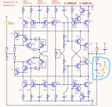
Elegant Circuit
The most elegant active differential I/V circuit I've yet seen is this one, by member Sergio Santos. Only 7-transistors, yet high performance. It also elegantly handles the output bias current of the PCM17xx DACs, integrating it as part of the total current conducted by the two biasing transistors. The output signal remains differential, however, and may require the anti-phase signals to be recombined, depending on your subsequent amplification chain.
https://www.diyaudio.com/forums/dig...convertion-low-distortion-95.html#post5767587
Hm, sorry my question was addressed to Sandy who built his circuit and must have listened to it.Sound perception can be different, because people have different hearing threshold and different listening skill.
If you think the specification is for the eye only, you do not understand the relationship of measurement and the sound perception.
May be for you, the right question is can you hear the sound different of the I/V converter that you mention BLINDLY?
Regarding to specifications vs. sound: I don't belong to those who defy the importance of specs. Normally I design first, then build and measure, then optimize for best parameters, and finally listen to it (and sometimes back to square 1). But I believe there is no linear relationship between measured parameters and listening experience above a certain level. And no, I did not listened to all I/V converters I mentioned - this is not my task. Currently I use an OPA627 (2 components) and I will upgrade to a transformer (also 2 components). Maybe I will try an I/V resistor + tube combo in the next decade

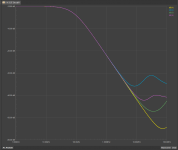
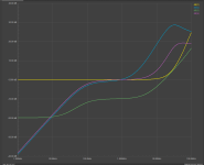
Here is the frequency response.
This is important because you have to integrate the high frequencies into the DAC output and they are > 10 MHz
And the input impedance in dB 0dB=1Ω
The best is the fastest operational amplifier.
But the noise of such amplifiers is very large for sound frequencies.
This is important because you have to integrate the high frequencies into the DAC output and they are > 10 MHz
And the input impedance in dB 0dB=1Ω
The best is the fastest operational amplifier.
But the noise of such amplifiers is very large for sound frequencies.
Attachments

- Home
- Source & Line
- Digital Line Level
- Discrete I-V converter