we have at the entrance +/- 1MA 5ns with a slope 1ns
And we observe the input and output
At the entrance
Best LM7171
Worst LT1468
At the exit
Best LM7171
Worst Discrete I/V
LM7171 has a great noise. That makes it not suitable
And we observe the input and output
At the entrance
Best LM7171
Worst LT1468
At the exit
Best LM7171
Worst Discrete I/V
LM7171 has a great noise. That makes it not suitable
Attachments

Buffer no longer has such high requirements and can do so with OPA1611, but still discreet is a little better.
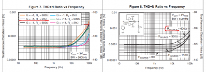
The noise of the buffer is the same as the OPA1611 in 3K filter resistances.
Thd of the discreet buffer are small on 100kHz.
OPA1611 data are for 600 ohms on the source, so for 3K will be even more.
The noise of the buffer is the same as the OPA1611 in 3K filter resistances.
Thd of the discreet buffer are small on 100kHz.
OPA1611 data are for 600 ohms on the source, so for 3K will be even more.
Attachments

I tend to agree with Syn08 that you have the same sort of behaviour as Petr-2009.we have at the entrance +/- 1MA 5ns with a slope 1ns
And we observe the input and output
At the entrance
Best LM7171
Worst LT1468
At the exit
Best LM7171
Worst Discrete I/V
LM7171 has a great noise. That makes it not suitable
You don’t listen to any argument against your theories and persist in pushing them against all odds.
One moment Opamps cannot be simulated and the next moment you include them and use insane 1mA 5nsec pulses with 1nsec risetime in a completely unrealistic attempt to prove that your design is superior.
On top of that, so far we have only seen simulations and not a single real life measurement although the base of your design is sound and used by many others, but they never gave measured distortion figures below 120dB in combination with the Dac, which by the way is more than enough.
Hans
Hansq
Again you did not understand what I was writing.
I wrote that you can not simulate credible THD of operating amplifiers.
Input, output resistance and frequency characteristics are simulated enough.
I'm only showing you the idea, not the finished product for it yet.
The parameters are so high that they cannot be measured without very special equipment.
On a generator with a fairly small THD, there is progress, but not completed THD can be reduced yet.
Such a DAC with such high parameters will be used for measurement mainly.
Last edited:
You remind me of another dear troll, petr_2009. Same style, same confusion between "measurement" and "simulation", same inability to respond to the most basic questions. Instead, an infinite monolog, leaving everybody with the same question: what is it that you want to prove?
Bingo
but a cfb mic amp beneffits of the input transistors gain...allowing the input trz some 100...400x gain and run the op-amp at 1...5x gain as it's also balanced design
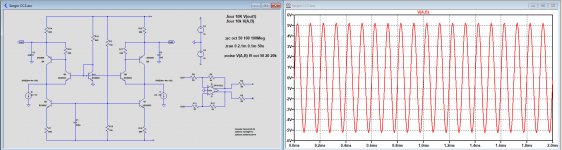
The output of PCM1794
Graph 3 is visible best.
Peaks with amplitude 1ma and time 2ns.
And this should be integrated accurately.
This overloads each integral audio operating amplifier.
Very true, the PCM179x family of DACs have extremely fast current edge rates, I've seen those images before.
Having said that, there are simple ways to slow the edge rates and ascertain whether the I-V opamp is misbehaving because of it.
In the case of 179x DAC's, it has been proven (on this forum) that the DACs linearity is not impaired with a small amount of voltage compliance on the
OP. As such a small CR or CL filter prior to I-V opamp can remove those super fast edge rates above audio frequencies.
I have only seen this done in one instance and the DAC's measurements were indeed very good. Was this purely the reason... who knows.
TCD
Buffer no longer has such high requirements and can do so with OPA1611, but still discreet is a little better.
The noise of the buffer is the same as the OPA1611 in 3K filter resistances.
Thd of the discreet buffer are small on 100kHz.
OPA1611 data are for 600 ohms on the source, so for 3K will be even more.
You have bootstrapped IP to discrete buffer, that is main advantage for this circuit.
TCD
On top of that, so far we have only seen simulations and not a single real life measurement although the base of your design is sound and used by many others, but they never gave measured distortion figures below 120dB in combination with the Dac, which by the way is more than enough.
So, you did not know that Syn08 built amplifier with THD 0.0001% at all audio frequency. He measured it.
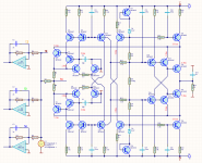
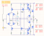
The most elegant active differential I/V circuit I've yet seen is this one, by member Sergio Santos. Only 7-transistors, yet high performance. It also elegantly handles the output bias current of the PCM17xx DACs, integrating it as part of the total current conducted by the two biasing transistors. The output signal remains differential, however, and may require the anti-phase signals to be recombined, depending on your subsequent amplification chain.
https://www.diyaudio.com/forums/dig...convertion-low-distortion-95.html#post5767587
Exactly!
This is a very simple but high performance I-V for 179x CCS OP type
converters however for SE OP the two phases need to be summed to achieve
those distortion numbers. Also an OP buffer would be nice.
TCD

6*-
Sergio has a talent for circuit topology. A single-ended version of his circuit is just as interesting, needing only 4 transistors, and giving a usably-low resistive output impedance without a buffer of 390 ohms.
Exactly!
This is a very simple but high performance I-V for 179x CCS OP type
converters however for SE OP the two phases need to be summed to achieve
those distortion numbers. Also an OP buffer would be nice.
TCD
Sergio has a talent for circuit topology. A single-ended version of his circuit is just as interesting, needing only 4 transistors, and giving a usably-low resistive output impedance without a buffer of 390 ohms.
Last edited:
The most elegant active differential I/V circuit I've yet seen is this one, by member Sergio Santos. Only 7-transistors, yet high performance. It also elegantly handles the output bias current of the PCM17xx DACs, integrating it as part of the total current conducted by the two biasing transistors. The output signal remains differential, however, and may require the anti-phase signals to be recombined, depending on your subsequent amplification chain.
https://www.diyaudio.com/forums/dig...convertion-low-distortion-95.html#post5767587
Ken,
That's indeed a very nice design for a current conveyor, thx for the link.
Fully differential in and out, and fully supporting the PCM179X including it's 6mA Bias, with only 3.5 transistor per channel.
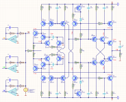
I have added a OPA1632 as a level shifter and for amplifying the signal a factor 2, giving 3.7Vrms in differential mode.
Noise is a low 2.9uVolt diff out and input resistance is below 1R up to 30Mhz.
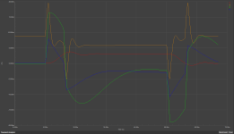
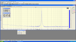
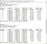
I have added the simmed THD figures, showing a very good -116dB from the first stage (0.000 152 %)
When combining both outputs which has to be done anyhow for SE and for Diff out, , the second harmonics are cancelled as can be seen in the image, giving a somewhat over the top -137dB THD, see second image (0.000 014%)
So let's say THD is a realistic -120dB, which is excellent for this design.
I'm considering to turn this into a PCB.
Hans
Attachments
- Home
- Source & Line
- Digital Line Level
- Discrete I-V converter