Thx, I'll look at it, good tip.
Maybe some resistors will have to be replaced by current sources.
Hans
Maybe some resistors will have to be replaced by current sources.
Hans
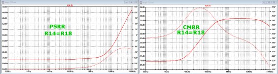
This is what LTSpice shows for PSRR and CMRR, measured at the output of the OPA1632.
Both channels are influenced the same way by power fluctuations potentially leading to a cancellation.
Even when giving both inputs a slightly different bias, nothing changes to the PSRR.
But the components having a high sensitivity for PSRR on the +15V side are the collector resistances R14 and R18. These should be within 0,01%
Negative supply PSRR is the same as the positive, but does not react on differences between R14 and R18.
CMRR is even more sensitve for the match between R14 and R18, so one of both should have a small pot included for tuning the CMRR at it's best value.
Automatically PSRR will then likely also be optimally tuned.
In the images below first the PSSR and CMRR in the optimal way, and the second image when R14 & R18 are 0.1% apart.
Any reason to distrust these figures ?
I will also investigate how a simple addition of current source may be beneficial to reduce this very high sensitivity.
Hans
.
Attachments

In the real world, the PSRR+ may not be that great.
True, but good supply regulation would go a long way to mitigating the low PSSR. Remaining noise on the supply+ would appear as common-mode across the two outputs and be rejected if sent to an following stage having good CMRR. Such as the differential amplifier Hans shows in his schematic. Modeling could quickly give some sense of the resulting PSRR, as well as some sense of the marginal PSRR improvement which active current-sources might provide.
Ken, having taken a first glimps at the above sims, I think that CMRR with all digital pollution is of greater concern than PSRR.
But as said, I will have a closer look at it tomorrow.
Hans
But as said, I will have a closer look at it tomorrow.
Hans
Adding current sources to V+ will obviously improve the PSRR and CMRR, but then the complexity increases to the point where a good dual op amp will be more economical (including board real estate) and without the matching pitfalls of a discrete implementation. I don’t see what this discrete implementation could do better than an OPA1612 and an OPA1632 (or, even better, a THS4551, if 5Vpp output is enough) if one needs level shifting.
P.S. I’m afraid thermal drift will also not be great. Dual transistors would be ideal, but probably still not enough. Ideally, the output drift should not exceed the DAC LSB, which is around 1uV. Not that it would be anywhere audible, but for an apple to apple discrete to op amp comparison it is worth considering.
P.S. I’m afraid thermal drift will also not be great. Dual transistors would be ideal, but probably still not enough. Ideally, the output drift should not exceed the DAC LSB, which is around 1uV. Not that it would be anywhere audible, but for an apple to apple discrete to op amp comparison it is worth considering.
Last edited:
Thx Syn08,
I have given this current conveyor design a fair try after my initial optimism.
It was a nice exercise, but especially the potentially very bad CMRR that worries me even more in this case then the PSRR, can't be reduced easily because common mode signals are amplified at open loop gain.
Only very cumbersome tuning of resistors can get this under control to some degree, but temp will detune this very easily.
I-V converters shown in this forum are mostly regarded as having to amplify only one Dac channel, but for Dac's with differential outputs, CMRR becomes all at the sudden very important making the choice between a current conveyors and fast opamps quite easy.
And of course PSRR with opamps is the least of your problems.
So I'm back to where I was originally.
Discrete I-V converter
Hans
Hans, did you actually listen to the current conveyor circuit before deciding to discard it?
Reason I ask is that CMRR may not always turn out to be all that subjectively important. Sometimes differential output dacs are used single ended, without any differential summing. In theory one might expect them to sound bad that way, but it doesn't always turn out to be the case in practice. Sometimes they end up sounding better than a dac using a standard 3-opamp output stage. Only way to find out is to try it for yourself and see what you think.
Reason I ask is that CMRR may not always turn out to be all that subjectively important. Sometimes differential output dacs are used single ended, without any differential summing. In theory one might expect them to sound bad that way, but it doesn't always turn out to be the case in practice. Sometimes they end up sounding better than a dac using a standard 3-opamp output stage. Only way to find out is to try it for yourself and see what you think.
Thx Syn08,
I have given this current conveyor design a fair try after my initial optimism.
It was a nice exercise, but especially the potentially very bad CMRR that worries me even more in this case then the PSRR, can't be reduced easily because common mode signals are amplified at open loop gain.
Only very cumbersome tuning of resistors can get this under control to some degree, but temp will detune this very easily.
I-V converters shown in this forum are mostly regarded as having to amplify only one Dac channel, but for Dac's with differential outputs, CMRR becomes all at the sudden very important making the choice between a current conveyors and fast opamps quite easy.
And of course PSRR with opamps is the least of your problems.
So I'm back to where I was originally.
Discrete I-V converter
Hans
Hans, I was thinking about how to increase the CMRR without significantly increasing circuit complexity. One thought I had, is to the two current biasing transistors with a single transistor common to both halves of the circuit. This would almost convert it in to long-tail differential current-conveyor. The most obvious issue would be the need for an impedance to separate the differential current DAC inputs. The first solution which comes to mind is to simply place a pair of resistors in series, across the differential current inputs. Then place an active current-source, connected from in-between the resistor pair down to the negative supply, functioning as a shared long-tail.
A pair of 160R resistors would drop only about 1 volt @ 6ma of DAC bias current, yet shunt only a relatively small amount of signal current away from the current-conveyor's input emitters. Differentially, 320R versus less than 2R.
Hans, did you actually listen to the current conveyor circuit before deciding to discard it?
Reason I ask is that CMRR may not always turn out to be all that subjectively important. Sometimes differential output dacs are used single ended, without any differential summing. In theory one might expect them to sound bad that way, but it doesn't always turn out to be the case in practice. Sometimes they end up sounding better than a dac using a standard 3-opamp output stage. Only way to find out is to try it for yourself and see what you think.
Without telling him how to set up such listening session, it's impossible to try and find out, no?

Hans, did you actually listen to the current conveyor circuit before deciding to discard it?
Reason I ask is that CMRR may not always turn out to be all that subjectively important. Sometimes differential output dacs are used single ended, without any differential summing. In theory one might expect them to sound bad that way, but it doesn't always turn out to be the case in practice. Sometimes they end up sounding better than a dac using a standard 3-opamp output stage. Only way to find out is to try it for yourself and see what you think.

is it any better then using a OPA 2134 or LME 49710 op amp as a I / V converter.
then use a 12ax7 to buffer the output and filter any HF hash out.
then use a 12ax7 to buffer the output and filter any HF hash out.
OPA2134 or a LM4562 (dual LM49710) would do fine as I/V, provided it would not have to drive a too low impedance (a few mA is ok). A tube output, I don't see what would be the advantage, you use an 0.0001% ultra low distortion op amp, than screw the setup with 0.1% or so of odd harmonics from an open loop tube stage.
You may enjoy the sound though, depending of your mood and the level of bourbon in your glass.
You may enjoy the sound though, depending of your mood and the level of bourbon in your glass.
I had second thoughts about the undocumented image of the Dac output signal that Sandy showed, giving transients of 1nsec.
Discrete I-V converter
Some people have to learn the hard way, well that's me.
On my multilayer PCB with carefully separated digital and analog ground planes, I terminated both PCM1792 outputs with very low induction 50R current sense resistors.
To this resistor I connected a 50R coax, terminated with a 50R feed through resistor on my scope, sampling at 2nsec intervals.
So in effect the Dac was terminated with 25R.
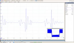
I offered a digital 1Khz -12dBFs square wave and measured the output of the Dac in the middle of the upgoing slope.
Image 1 below shows the recording over a 15usec period, giving a good impression of the nature of the signal generated by the Dac.
The second image shows a further magnified timescale to 20nsec/div.
There are transients of 2nsec to be seen, so my scope is not fast enough to capture this signal more accurately.
But pulses are obviously and indeed in the low nsec range.
The ca 40mV transients correspond to almost +/ -1mA peaks from the Dac.
Important question now to answer is, what requirement does this pose on the I-V converter.
A converter at this frequency will likely have the same sort of 25R Zin, so it's input will see 40mV voltage excursions that it can't follow.
Can this possibly do any harm, I don't think.
To my feeling a fast opamp like the LT1468 or the OPA1612, already standard equiped with proper input overloads protection should be able to cope with these pulses.
Anybody doesn't agree ? I welcome any kind of comment.
Hans
.
Discrete I-V converter
Some people have to learn the hard way, well that's me.
On my multilayer PCB with carefully separated digital and analog ground planes, I terminated both PCM1792 outputs with very low induction 50R current sense resistors.
To this resistor I connected a 50R coax, terminated with a 50R feed through resistor on my scope, sampling at 2nsec intervals.
So in effect the Dac was terminated with 25R.
I offered a digital 1Khz -12dBFs square wave and measured the output of the Dac in the middle of the upgoing slope.
Image 1 below shows the recording over a 15usec period, giving a good impression of the nature of the signal generated by the Dac.
The second image shows a further magnified timescale to 20nsec/div.
There are transients of 2nsec to be seen, so my scope is not fast enough to capture this signal more accurately.
But pulses are obviously and indeed in the low nsec range.
The ca 40mV transients correspond to almost +/ -1mA peaks from the Dac.
Important question now to answer is, what requirement does this pose on the I-V converter.
A converter at this frequency will likely have the same sort of 25R Zin, so it's input will see 40mV voltage excursions that it can't follow.
Can this possibly do any harm, I don't think.
To my feeling a fast opamp like the LT1468 or the OPA1612, already standard equiped with proper input overloads protection should be able to cope with these pulses.
Anybody doesn't agree ? I welcome any kind of comment.
Hans
.
Attachments

Ken,Hans, I was thinking about how to increase the CMRR without significantly increasing circuit complexity. One thought I had, is to the two current biasing transistors with a single transistor common to both halves of the circuit. This would almost convert it in to long-tail differential current-conveyor. The most obvious issue would be the need for an impedance to separate the differential current DAC inputs. The first solution which comes to mind is to simply place a pair of resistors in series, across the differential current inputs. Then place an active current-source, connected from in-between the resistor pair down to the negative supply, functioning as a shared long-tail.
A pair of 160R resistors would drop only about 1 volt @ 6ma of DAC bias current, yet shunt only a relatively small amount of signal current away from the current-conveyor's input emitters. Differentially, 320R versus less than 2R.
I tried many options and succeeded to improve things.
Very vital are the two 2n2 caps that should be replaced by 1n between outputs, no longer disturbing CMRR with a mismatch between the two.
The same can be done with the two 390R collector resistors, to be replaced by one 820R between outputs and two current sources, and giving the OPA1632 low value input resistors.
However the problem only shifts from one place to another and it seems almost impossible to get CMRR under control without serious addition of extra hardware.
So I gave up.
As mentioned I was charmed by the simple design, too optimistic to start with and did not directly get a feeling for these high sensitivities.
But never too late, I learned my lesson and will stick to my opamp solution.
Hans
I did some further measurements on the PCM1792 Dac output with a voltage feedback amp, compared at the same time to a 25R resistor.
And finally did a sim to compare this vs real measured results.
This showed IMO that opamps are not modelled well enough for this kind of situations.
What do you think makes NOS sound different?
Hans
And finally did a sim to compare this vs real measured results.
This showed IMO that opamps are not modelled well enough for this kind of situations.
What do you think makes NOS sound different?
Hans
What probe are you using for these measurements? Do you have an <1pF probe to reliable see those spikes? I’ve seen way too many scope/probe artifacts, and what an improper probe can do to a signal, to trust such short (2nS) events having much to do with the truth. Think of a 10pF probe as added to an allegedly carefully matched coax...
I agree that such a measurement can be quite tricky, that’s why I didn’t use a probe.
Connected at less than 5mm distance to the 50R low induction resistor over the Dac’s output I mounted a coax socket.
A 1 meter RG58C/U 50R coax cable from here entered a DC to 1Ghz 50R feed-through termininator at the scope’s 1Meg//8pF input.
Do you see any way to improve this, I’m open for suggestions.
Hans

- Home
- Source & Line
- Digital Line Level
- Discrete I-V converter