And finally did a sim to compare this vs real measured results.
This showed IMO that opamps are not modelled well enough for this kind of situations.
Hans
I’m sorry, but your information is simply wrong.
Simulation results with modern low noise high speed opamps are most of the time just as accurate as results with discrete circuits, meaning that results with both may be on the optimistic side and everything under -120dB has to be taken with a big corn of salt.
Hans
Never late to learn.
did you apply the 20khz differential LPF filter like in the pcm1792 data with their lt1028 or similar op-amp too?
Thx for sending.
This LT1028 filter is at 200Khz.
Instead of the LT1028 I use the OPA1632 with four 1K resistors and yes I also tried with two 1nF caps which reduces HF.
Mind you that TI at later instances advised even 300Khz filters.
https://www.ti.com/lit/an/sboa237/s...953343&ref_url=https%3A%2F%2Fwww.google.nl%2F
Hans
So this is the idle output current and the idle output voltage after the I/V.
What DAC is this? What you see at 82nS could be an oversampling effect, although x64 would be unusual, x128 would be more common (24.576MHz). Are you sure there is no parasitic coupling with the MCLK? Those pulses look like a differentiated clock signal...
Dac is the PCM1792.
Even when the pulse were being from parasitic coupling with the MCLK, the image with the 10Mhz filtered signals with suppresed pulses leave IMO no other possible conclusion that in this case the Dac switches it’s output at 82nsec intervals.
Hans
Never late to learn.
Quote:
Simulation results with modern low noise high speed opamps are most of the time just as accurate as results with discrete circuits,
Quote:
opamps are not modelled well enough for this kind of situations.
Given your last quote i thought that maybe op-amps like ADA4898 would have some better models for LtSpice ,yet couldn't find it in my library so I used the ada4896 instead (SR=120v/us) and what i can see is just some fantastically stable op-amps compared with LT1462, which i'm not that sure of ...
Attachments

Last edited:
maybe that's to improve the q of the filter at higher frequencies...Thx for sending.
Mind you that TI at later instances advised even 300Khz filters.
https://www.ti.com/lit/an/sboa237/s...953343&ref_url=https%3A%2F%2Fwww.google.nl%2F
Hans
Given your last quote i thought that maybe op-amps like ADA4898 would have some better models for LtSpice ,yet couldn't find it in my library so I used the ada4896 instead (SR=120v/us) and what i can see is just some fantastically stable op-amps compared with LT1462, which i'm not that sure of ...
IMO input impedance for those transients is the most important parameter, more important than slew rate.
25V/usec should most likely be enough.
I’m going to connect a 50R impedance to the virtual input of the LT1468 in series with coax and feedthrough termination.
That way I hope to be able to see what input voltage the current transients are causing at the amps input.
Hans
I forgot that pcm1792 has an output of 4ma.so now my results are 4 times higher so your results are about 12...16 times smaller.
Now if i use a voltage source into a 1 kohm resistor to approximate 4ma plus 1 kohm dac output impedance , those 50 ohm in series with 1 kohm will give me almost the same output.If i use a pure current source with probably zero ohm impedance i get no different results...Here my sim is completely useless.
Now if i use a voltage source into a 1 kohm resistor to approximate 4ma plus 1 kohm dac output impedance , those 50 ohm in series with 1 kohm will give me almost the same output.If i use a pure current source with probably zero ohm impedance i get no different results...Here my sim is completely useless.
If i use a pure current source with probably zero ohm impedance i get no different results...Here my sim is completely useless.
Why do you do that?
The output Z of a current source should be as high as possible not Zero.
A voltage source should have as low output Z as possible.
The output of the DAC is probably an open collector NPN or an open drain NMOS and the output Z should be as high as possible, you could use a common base stage as the first stage that the DAC "sees" to increase the Z and make it easier for the DAC.
Dac is the PCM1792.
Even when the pulse were being from parasitic coupling with the MCLK, the image with the 10Mhz filtered signals with suppresed pulses leave IMO no other possible conclusion that in this case the Dac switches it’s output at 82nsec intervals.
I must be missing something obvious here, how come a 10MHz (LPF, I presume) at the output leaves 82nS apart pulses? 82nS period is about 12MHz.
What are the pulses in #183 first pic?
Last edited:
I think I did it, at last.
50R low induction was connected on one side to the virt. gnd input of the LT1468.
The other side went into a coax line that was terminated with 50R at the scope's input.
Virtual gnd input in that set-up saw a additional 100R load, while the signal at the scope was divided by two.
At the same time the output signal was recorded as before at the output of the I-V, not showing any difference with or without the 100R+coax connected as a confirmation that all went as hoped for.
I could finally see the real signal at the LT1468's input, while now at the same time knowing that the Dac produces 2nsec transients of +/-1mA.
In the image below, the blue signal at the scope's input as caused by the Dac, never became larger as +/-12mV, with these +/-1mA transients from the Dac.
At the virt. gnd input the signal is now twice as large with +/- 24mV, leading to the conclusion that the impedance including 100R scope load for these 2nsec transients is 24mV/1mA=24R.
Taking the 100R scope load out of the equation, Zin now calculates as 32R that will result in transients at the input of +/-32mV, way below the point were the LT1468's input will get overloaded.
So here ends my series of measurements, while having confirmed that everything seems O.K.
Hans
.
Attachments
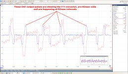
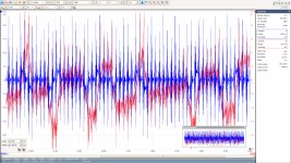
In the image below, the blue 82nsec wide pulses from the DAC, smoothened because of the 10Mhz LP filter, are the ones holding the content information and are steering the I-V converter, which output is in red.I must be missing something obvious here, how come a 10MHz (LPF, I presume) at the output leaves 82nS apart pulses? 82nS period is about 12MHz.
Hans
.
Attachments
Sorry Hans, I fail to understand how those 82nS pulses passed through a 10MHz LPF. Likely, I don't understand your measurement setup and your procedure. You described it several times, but for me it still doesn't compile. A schematic with all the elements, signals and the measurement points would go a long way, but don't bother, I can live without more details, anyway.
Last edited:
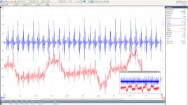
The 10Mhz filter is not exactly a brick wall filter but a just a simple first order filter, attenuating 12Mhz maybe by only a few dB.
But when looking at the unfiltered version, one can clearly see the same 82nses pulses but now burried in transients..
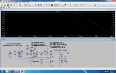
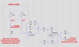
See both images below showing the exact same recording with and without filtering but on a different vertical scale.
The measurement set-up is in the third image.
Hans
.
But when looking at the unfiltered version, one can clearly see the same 82nses pulses but now burried in transients..
See both images below showing the exact same recording with and without filtering but on a different vertical scale.
The measurement set-up is in the third image.
Hans
.
Attachments
Last edited:
So blue is channel A and red is channel B, correct? How do you connect channel B, since the output is differential and the scope input is single ended?
Yes, blue is Channel A and red is Channel B.
The scope's Channel B is only connected to one output of the OPA1632.
There is a diff output but also a SE output at my DAC, so I used this SE output for the measurement and connected it via a coax cable to the scope.
Hans
The scope's Channel B is only connected to one output of the OPA1632.
There is a diff output but also a SE output at my DAC, so I used this SE output for the measurement and connected it via a coax cable to the scope.
Hans
So B is attenuated by a factor of 1/3 by the channel B measurement setup? 50ohm/(100ohm + 50ohm)? I am wondering why the gains don't add up.
Dac current for Channel A goes into 25R.
The other halve of the Dac's current output is converted in a 1K resistor over the LT1468.
Since the OPA1632 in this setup is connected with one input to gnd, the SE output that I use, attenuates the output from the LT1468 by 0.5.
Difference in gain between the two channels is therefore (1k*0.5)/25 = 20.
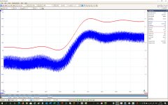
When idling this is not easy to check, but when applying a square wave it is easy to see that the Channel B has a 20 times larger vert scale as Channel A, resp 400mV/div and 20mV/div.
Hans
.
The other halve of the Dac's current output is converted in a 1K resistor over the LT1468.
Since the OPA1632 in this setup is connected with one input to gnd, the SE output that I use, attenuates the output from the LT1468 by 0.5.
Difference in gain between the two channels is therefore (1k*0.5)/25 = 20.
When idling this is not easy to check, but when applying a square wave it is easy to see that the Channel B has a 20 times larger vert scale as Channel A, resp 400mV/div and 20mV/div.
Hans
.
Attachments
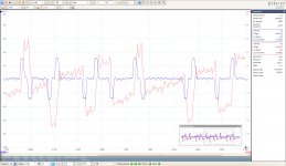
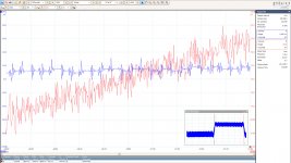
And when zooming very strong into the slope, it is still possible but a bit harder to see gain of 20 because both sides have 20mV/div vertically.
But now the 82nsec pulses from the Dac are visible again.
Hans
.
But now the 82nsec pulses from the Dac are visible again.
Hans
.
Attachments
Last edited:
- Home
- Source & Line
- Digital Line Level
- Discrete I-V converter