It also shows that circumventing the internal up-sample filter, does not really turn the PCM179X into a NOS Dac, because the 8Fs upsampler stays always in action.
Hans
.
The internal 8 x up sampling filter does not always stay in action. 179x can
be fed directly from external 8 x OS digital filter outputting 384k 768k etc. If
what you say is true, this would not be possible.
Maybe you are confusing this with modulator speed which is 64 x FS(44.1 / 48) or in the 1792's case 64 / 128 x FS
TCD
TCD,
When you could directly feed the Dac with 8Fs oversampling, you still had to oversample externally.
However the fact sheet tells that for PCM Fs max is 200Khz, so could it be that you are confused with the max clock frequency ?
The point I was trying to make is that you can never make a real NOS Dac from a PCM179X, not because of the 8Fs oversampling plus SDM and not because of images appearing at multiples of 8Fs instead of Fs.
Hans
Last edited:
Can't you use an external digital filter with impulse response 1, 1, 1, 1, 1, 1, 1, 1, so just repeat the same sample eight times? Of course it's still not real non-oversampling because of the sigma-delta, but at least you get the sinc droop and all the ultrasonic images back and solve or much reduce the intersample overshoot issues.
Last edited:
I’m afraid I don’t get what you mean.
Repeating each sample eight times externally would give a sample rate of 8*44.1Khz, while Fs max for Dac is 200Khz.
Hans
Repeating each sample eight times externally would give a sample rate of 8*44.1Khz, while Fs max for Dac is 200Khz.
Hans
See pages 38...41 of the PCM1792A datasheet, revised November 2006. It's a different interface than the normal PCM interface.
@ Marcel,
I believe to understand that you mean that by increasing the bit clock (and system clock - in your example by 8) you are increasing the speed of the SD modulator. yes, than it makes sense to repeat the samples at the same time you increase the clock signals. the corner frequency of the q-noise will shift up in the spectrum
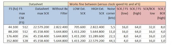
I measured this some time ago with "no digital filter" mode and I2S input running at several FS frequencies and matched an external clock signal to SCK pin till the sound was actually ok (can be done for testing, works fine - not for listening as it drifts away at some point and starts clicking)
below is the result - it was kind of interesting to see that the DAC chip / modulator also works when the SCK system clock is BELOW the bit clock BCK 😱
also there is a maximum. after that the modulator is not working for that FS. Actually this the BCK...
Of course the corner of the noise curve (flat below going up after that) is clearly in the audio band when playing
I only did this to get a better understanding of the internal working of the PCM chip
.
I believe to understand that you mean that by increasing the bit clock (and system clock - in your example by 8) you are increasing the speed of the SD modulator. yes, than it makes sense to repeat the samples at the same time you increase the clock signals. the corner frequency of the q-noise will shift up in the spectrum
I measured this some time ago with "no digital filter" mode and I2S input running at several FS frequencies and matched an external clock signal to SCK pin till the sound was actually ok (can be done for testing, works fine - not for listening as it drifts away at some point and starts clicking)
below is the result - it was kind of interesting to see that the DAC chip / modulator also works when the SCK system clock is BELOW the bit clock BCK 😱
also there is a maximum. after that the modulator is not working for that FS. Actually this the BCK...
Of course the corner of the noise curve (flat below going up after that) is clearly in the audio band when playing
I only did this to get a better understanding of the internal working of the PCM chip
.
Attachments
I’m afraid I don’t get what you mean.
Repeating each sample eight times externally would give a sample rate of 8*44.1Khz, while Fs max for Dac is 200Khz.
Hans
in no digital filter mode you can go higher as long as you keep BCK=SCK
I play without any problems up to 384kHz tracks. see also my post below
To TCD, Marcel and DDAC
I now see that the function to use an external filter applies to the 8Fs filter before the SDM, making it possible to offer much higher speeds as 200Khz
I’ll have to reread the documentation again in more detail.
Hans
I now see that the function to use an external filter applies to the 8Fs filter before the SDM, making it possible to offer much higher speeds as 200Khz
I’ll have to reread the documentation again in more detail.
Hans
@ Marcel,
I believe to understand that you mean that by increasing the bit clock (and system clock - in your example by 8) you are increasing the speed of the SD modulator. yes, than it makes sense to repeat the samples at the same time you increase the clock signals. the corner frequency of the q-noise will shift up in the spectrum
I measured this some time ago with "no digital filter" mode and I2S input running at several FS frequencies and matched an external clock signal to SCK pin till the sound was actually ok (can be done for testing, works fine - not for listening as it drifts away at some point and starts clicking)
below is the result - it was kind of interesting to see that the DAC chip / modulator also works when the SCK system clock is BELOW the bit clock BCK 😱
also there is a maximum. after that the modulator is not working for that FS. Actually this the BCK...
Of course the corner of the noise curve (flat below going up after that) is clearly in the audio band when playing
I only did this to get a better understanding of the internal working of the PCM chip
.
I never used a PCM179x, but as it is meant to work with either an internal or an external eight times oversampling filter, using an external filter that just repeats the same sample eight times seems to be a way to approximate a non-oversampled waveform. I gather from your response that you don't repeat any samples and just let the sigma-delta run at a lower rate than it was meant for, and that you determined experimentally how fast you can then let it run and what that does to the audio noise.
Yes Marcel, that was and is the concept of the DDDAC… run it from straight I2S input in non digital filter and use BCK as system clock.
The Modulator runs slower, nevertheless the results were and are surprisingly good.
I am working on an experimental prototype setup where the clock is close to the pcm chip and can be selected at all kind of frequencies/speeds x1 up to :16 in two magnitudes and use this also as master clock for the I2S generation, in this case a FIFOPI - I am just wondering how it would measure and how that would sound. Finding a way to optimize the DS modulator speed in the PCM das chip for the corresponding FS rate ….
But I stop going off topic here (sorry !) and when time comes make an own thread for this
I never used a PCM179x, but as it is meant to work with either an internal or an external eight times oversampling filter, using an external filter that just repeats the same sample eight times seems to be a way to approximate a non-oversampled waveform. I gather from your response that you don't repeat any samples and just let the sigma-delta run at a lower rate than it was meant for, and that you determined experimentally how fast you can then let it run and what that does to the audio noise.
I also never made a Dac with the PCM179x, but happen to have a Dac with this chip inside.
My objective was to find out whether a fast opa could handle the signal from the Dac without getting overloaded and regarded the 1792 as a black box and also measured images at multiples of 8Fs.
My big mistake was that without being interested in too much detail, I assumed that the Dac also performed the upsampling to 192Khz before doing the 8Fs.
But because of this ongoing discussion, I now see that the 8Fs up-sampler is the only up-sampler that’s there in the 1792 and upsampling to Fs is performed by the Asrc in front of the Dac, in my case a SRC4392.
So the trick as mentioned by Marcel by repeating the incoming sample 8 times at 8Fs is the closest you can get to a NOS Dac with a PCM179X.
Thank you Marcel for making me aware of the 8Fs details.
Hans
...So the trick as mentioned by Marcel by repeating the incoming sample 8 times at 8Fs is the closest you can get to a NOS Dac with a PCM179X..............
or use BCK as SCK
or use BCK as SCK
DDDAC,
You are probably the man with the most PCM1792 hands on experience.
Just for my understanding, does your suggestion mean in case of a 44.1K file to use a 32*44.1Khz SCK, identical to the BCK to let the Dac process the incoming data thinking it is at 8Fs.
If so that would mean that the SDM runs at 8*44.1k = 352.8Khz or ca. 3usec for each Dac output update, making the nsec current transients at the beginning of each switch totally irrelevant, true ?
Hans
Can't you use an external digital filter with impulse response 1, 1, 1, 1, 1, 1, 1, 1, so just repeat the same sample eight times? Of course it's still not real non-oversampling because of the sigma-delta, but at least you get the sinc droop and all the ultrasonic images back and solve or much reduce the intersample overshoot issues.
Marcel, I seem to recall that you may have some SDM design experience.
If so, perhaps, you can address a question which seems to be causing a little bit of confusion, at least, it is for me. This is in regards to whether, or not, SDM can be fairly referred to as subjectively NOS. There seems some conflation between upsampling via FIR interpolation, and upsampling via SDM operation. Since FIR filters utilize a form of discrete-time feedforward, while (I thought) SDM utilizes a form of discrete-time feedback, aren't they two dissimilar processes, and should not be conflated?
I'm not sure if this answers your question, but:
1. A sigma-delta modulator has to work at a clock frequency much greater than twice the highest signal frequency of interest to get a decent amount of noise shaping, so in that sense it is always oversampled.
2. You can look at a digital sigma-delta modulator as a kind of IIR filter with a very coarse requantization in its loop. The signal transfer from input to output, usually called the STF (signal transfer function), can be an all-pole low-pass transfer or there can be additional zeros in it, depending on the design. One can even cover all poles with zeros and have a unity signal transfer function.
In any case, the poles of the signal transfer function are also the poles of the noise transfer function (NTF), a high-pass transfer function that describes the transfer from quantization noise to the output. They determine at what frequency the NTF levels off, and that has to be far above the audio band to get a decent amount of noise suppression at audio frequencies. It's usually of the order of some hundreds of kilohertz for an audio converter.
All in all, the STF will usually either be an all-pole minimum-phase low-pass transfer with a bandwidth of hundreds of kilohertz, or a minimum-phase transfer that peaks and then rolls off at hundreds of kilohertz, or a perfectly flat response. None of them look anything like a brick-wall linear-phase filter at or just above 20 kHz.
DDDAC,
You are probably the man with the most PCM1792 hands on experience.
Just for my understanding, does your suggestion mean in case of a 44.1K file to use a 32*44.1Khz SCK, identical to the BCK to let the Dac process the incoming data thinking it is at 8Fs.
If so that would mean that the SDM runs at 8*44.1k = 352.8Khz or ca. 3usec for each Dac output update, making the nsec current transients at the beginning of each switch totally irrelevant, true ?
Hans
almost Hans, the PCM179x works with 2 x 32 bits so it is 64 x 44.1 = 2,822 MHz I can see on my scope that every BCK the current changes and there is a little current peak with same polarity. Looking at supposed pF in the Probe and board and the 1mA you mentioned and the passive load of 133 Ohm (I use with one deck passive I/V) I expected a few 100mV peak and indeed that is visible. Due to the scope I use it rings a bit round 100Mhz, but that is the test setup. so it is every 354 nsec.
I really doubt if you can hear this. In the the listening to audio setup I am using a TVC behind this which filters a lot of HF of course. For the test I had OPT, measure straight without any filtering
If you would put an opamp at the I/V, (this thread topic?) you might run in other problems, but as said, I am not using any opamps in my chain, other than DC servo control 😀
.
Doede,
Thx for trying to clarify, but I don't get those figures together.
In NOS mode the 179X has separate inputs for L and R, so in parallel mode a 32*44,1Khz would do as BCK, but since you mention to need 64*44.1Khz, it seems that L + R have to be offered sequentially instead.
But now offering data to the SDM at Fs=44.1Khz, I would expect the SDM to run at 8Fs or optionally even at 16Fs at resp. 352.8Khz or 705.6Khz giving times slots for each new sample of resp. ca 2.8usec or 1.4usec.
However, if I got it right, you mentioned to see on your scope updates every 354nsec and that's exactly 8 times faster as the expected 2.8usec, namely the 2.822Mhz SCK.
So could it be that what you see is crosstalk from the BCK/SCK, or did you indeed refer to this BCK/SCK with the 354nsec ?
Hans
Last edited:
Hi Hans,
the I2S protocol just delivers BCK = 64 x FS. Left and Right channel data are intermediating. that is regardless which chip you feed with it. hence the 2,8224 Mhz I refer to when playing 44.1 tracks
Now the point of updating is something I cannot 100% say for sure. I do see the small peak, but if this the 1mA you mention or some cross talk is a chicken and egg thing, I don't know (yet) how to get my finger behind...
Hi Doede,
Probably the easiest way to get your finger behind it, is to let the Dac idle at 44.1Khz and look for peaks occuring every 2.8 usec.
But you will need a very fast scope sampling at least at 1nsec intervals to catch those 2nsec transients.
But in your case transients lasting only a couple of nanoseconds every 2.8usec are completely insignificant, so it’s only of academic interest.
Hans
Here is the effect of using 0.1% resistors and 1% caps on all the critical places.
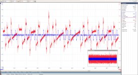
In blue the signal on the 25R resistor attached to Iout+ of the L channel and in red the SE output of the R channel after I/V conversion with LT1468 and 1K//1nF feedback, both I/V sides turned into a SE signal with a OPA1632.
Difference in gain between L and R is 1K/25=40.
While the signals are not synchronised because not from the same channel, the 81.38nsec slots from the Dac are well visible, in this case filtered at 30Mhz to remove the 2nsec transients for better visibility.
And the non filtered response at the SE output shows that only some peaking is visible when the output value has to change , but the 2nsec transients every 81.38nsec are effectively suppressed by the CMRR of the OPA1632 and the well matched I/V converters.
Hans
Attachments
Last edited:
- Home
- Source & Line
- Digital Line Level
- Discrete I-V converter