Yes there are.To go a little in the opposite direction, the picture shows my I / V stage and output buffer. 6HM5 is in the grounded grid. The signal ie current from PCM1702 comes to the cathode of the tube.
A long time ago I left discrete and op amp I / V conversion and I replaced it with tubes. I tried everything, even the AD811, but the sound of the tube was much better for me.
However now I am working on a new DAC with TDA1547 where I will have to use discrete or op amp I / V conversion if I intend to use only current outputs, I also have two PCM1794 on hold which in mono mode does not have a suitable tube that could do I / V conversion in a grounded conection.
But I agree that PCM179x is by strict terminology, a 'current source' DAC where as a 'current sink' DAC (internal N channel device OP stage) would make things a little easier.
All you need is an appropriate SS CCS loading a beefy enough tube with high enough gm and current capacity and it will work... very well at that.
TCD
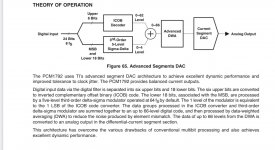
One last piece of information to share concerning the PCM179X.
As earlier shown is that at 81.38nsec intervals a new current can be produced at the Dac's output.
Also shown is that regardless whether the new current is the same or not as in the previous time slot, 1mA@2nsec pulses are generated from switching to the next value.
What I can now add to that, is that these 1mA@2nsec pulses are of equal polarity for Iout+ and Iout-.
This means that it is important to get the CMRR as good as possible, meaning preferably the use of 0.1% resistors for the I-V conversion and 1% caps for the cap parallel to this resistor.
Hans
One last piece of information to share concerning the PCM179X.
As earlier shown is that at 81.38nsec intervals a new current can be produced at the Dac's output.
Also shown is that regardless whether the new current is the same or not as in the previous time slot, 1mA@2nsec pulses are generated from switching to the next value.
What I can now add to that, is that these 1mA@2nsec pulses are of equal polarity for Iout+ and Iout-.
This means that it is important to get the CMRR as good as possible, meaning preferably the use of 0.1% resistors for the I-V conversion and 1% caps for the cap parallel to this resistor.
Hans
Hans, how closely are these equal polarity pulses phase-aligned?
Ken,
For what I can estimate the same in time, but also in amplitude.
However my scope samples 2 channels at 2nsec intervals with 1nsec interleaved, so to be even more exact with 2nsec transients I would need a much faster scope.
But I take that for granted and simply go for accurate component values.
Hans
To further support the fact that the transients are at exactly the same moment; the masterclock is at 24.576 Mhz.
So when one transient would be at the upgoing clock slope and the other transient at the downgoing one, there would be a time difference of 20nsec between the two transients.
However there is only 1nsec between the two, ergo they must be caused by the same clock slope.
Hans
So when one transient would be at the upgoing clock slope and the other transient at the downgoing one, there would be a time difference of 20nsec between the two transients.
However there is only 1nsec between the two, ergo they must be caused by the same clock slope.
Hans
One last piece of information to share concerning the PCM179X.
As earlier shown is that at 81.38nsec intervals a new current can be produced at the Dac's output.
Also shown is that regardless whether the new current is the same or not as in the previous time slot, 1mA@2nsec pulses are generated from switching to the next value.
What I can now add to that, is that these 1mA@2nsec pulses are of equal polarity for Iout+ and Iout-.
This means that it is important to get the CMRR as good as possible, meaning preferably the use of 0.1% resistors for the I-V conversion and 1% caps for the cap parallel to this resistor.
Hans
Interesting Hans, this equals to 12,288 MHz- like masterclock for 48kHz FS. did you measure this value of 81 ns playing indeed 48kHz track. Did it change when playing other FS tracks ?
No, the 81.38 nsec did never change in my case, but this has everything to do with the fact that my Bel Canto Dac is programmed to convert all incoming content to 192Khz.
Hans
Hans

Ok got it. If FS =192 then bck is 12,288 MHz. So is bck causing this then ?
System clock offered to my PCM1792 is 24.576 Mhz.
The sigma delta modulator is working at halve this frequency which has no direct relation with the bck.
Hans
.
Attachments
In order for an operational amplifier to filter out one frequency, its FT must be at least 10 times greater in order to have at least 10 times Ku at this frequency.
Sandy,
I don’t get what you want to say with the shown table, but my system clock is with 128Fs at 24.576 Mhz, the SDM outputs it’s current at halve this frequency and the LT1468 that I use has a BW 8 times as high.
Could you still answer my question how and where the recording was made with the 2nsec 1mA current output pulses that you showed.
Hans
Thanks Hans for clarifications. Makes perfect sense. I will see if I can measure anything similar….
1. even if there is only 1ns difference it wouldn't be possible to eliminate them with a subtraction.To further support the fact that the transients are at exactly the same moment; the masterclock is at 24.576 Mhz.
So when one transient would be at the upgoing clock slope and the other transient at the downgoing one, there would be a time difference of 20nsec between the two transients.
However there is only 1nsec between the two, ergo they must be caused by the same clock slope.
Hans
2. IMHO the spikes are caused by switching off only., since they are of the same polarity. Some current sources are switched off in the other channel too.
3. There seem to be switched a couple of CS(5 or 6) consecutively with different spike highs in one master cycle. they are arranged that the higher bits are switched in the middle of the cycle.
Last edited:
Your measurements showed that these peaks exist, and their order and almost the same.Sandy,
I don’t get what you want to say with the shown table, but my system clock is with 128Fs at 24.576 Mhz, the SDM outputs it’s current at halve this frequency and the LT1468 that I use has a BW 8 times as high.
Could you still answer my question how and where the recording was made with the 2nsec 1mA current output pulses that you showed.
Hans
And a low (Ft) operating amplifier from 1-2GHz can not filter them.
With an oscilloscope, it is no longer possible to measure.
It must be measured by a spectrum analyzer (FFT) and measured (IMD)
Attachments
Ah at last, there’s the original document with measurements.
Looks interesting, thx.
I’ll try to translate it and post it back in English.
Hans
Yes, but in this case the 1nsec is caused by the alternating sampling between channels with 1nsec intervals.1. even if there is only 1ns difference it wouldn't be possible to eliminate them with a subtraction.
And while the transients are clock driven by the same clock, they must occur at exactly the same moment.
Could be, but doesn’t look that way on the scope.2. IMHO the spikes are caused by switching off only., since they are of the same polarity. Some current sources are switched off in the other channel too.
Switching of the current sounds as if for a short while no current is flowing, which is absolutely not the case.
We simply have no idea of the mechanism behind.
May I call this another wild guess based on images from a 200Mhz scope that is sampling 1Gs/sec, way too slow to draw conclusions as you are suggesting ?3. There seem to be switched a couple of CS(5 or 6) consecutively with different spike highs in one master cycle. they are arranged that the higher bits are switched in the middle of the cycle.
Hans
Sandy,
I have translated the document from Valery Sergeev.
1) He is using the same definition as Petr_2009 that all graphical change in waveform is called distortion.
Pre and post ringing makes the shape of a dirac pulse different, but it is caused by removing the supersonics by sinc filtering and has nothing to do with distortion in the electronic sense.
A perfect linear filtering process does not cause distortion as is defined in Audio.
2) He compares a multibit 1704 NOS Dac with a 1794 SDM Dac in NOS setting that does however up-sample to 8Fs for the highest 6 bits and SDM for the lower bits at 64Fs, resulting in incomparable results that cannot be used to prove the superiority of a R-2R Dac the way he tried.
3) to produce image 16 & 17 he must have had access to a professional 4Gs/sec scope, but his measurement set-up and the tools he used are not mentioned.
Out of the blue he mentions that
4) "It must be assumed that any asynchronous resampling to a higher frequency will significantly distort the waveform.
5) "Multibit PCM1704 is the only commercially available honest audio Dac."
6) "We can safely recommend the PCM1794 with the exception for Ultra Hi-Fi"
Hans
.
Attachments
Honnest to what ? Cause for the ears I find a less resolved on paper 20 bits AD1862 to sound better as well as the simple 16 bits TDA1541A.
As usual there is not always correlation with measurement protocol and how it translates in hearing quality perceived with complex materials, not saying about the testing protocol itself.
Are there some tests with old Sigma Delta NPC chip that has no embeded audio analog filter on its voltage outputs ?
The article is loaded with wrong assumptions and non founded opinions, isn’t it !Honnest to what ?
Hans
Interesting Hans, this equals to 12,288 MHz- like masterclock for 48kHz FS. did you measure this value of 81 ns playing indeed 48kHz track. Did it change when playing other FS tracks ?
I can be more concrete after having examined the PCM179X in greater detail.
The 81.38nsec was based on the following:
Up-sampling in my case was to Fs=192Khz.
From thereon the signal is further up-sampled to 8Fs and fed to a 6 bit Dac, converting these 6 MSB's.
The lower bits are going into a 5 level SDM operating at 64Fs and added to the upper 6 bit results.
Output in that case is at every 1/(192KHz*64)= 81.38nsec.
Now take a setting without using the up-sample filter, like as a sort of NOS Dac.
Output is now every 1/(44.1Khz*64)=0.35usec.
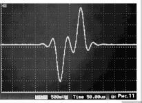
See second image below how two dirac pulses with opposite polarity and one period rest in between are processed by the PCM179X Dac.
This image was produced by Valery Sergeev.
Note that the staircase steps that you see are not caused by the Dac, but by the 8 bit scope resolution.
First image pair in this setting will now be at 8Fs or 352.8Khz instead of 44.1Khz for a Multibit NOS Dac. So from 22.05KHz to 330.75Khz there is no content assuming adequate suppression by the 8Fs up-sampler.
It also shows that circumventing the internal up-sample filter, does not really turn the PCM179X into a NOS Dac, because the 8Fs upsampler stays always in action.
Hans
.
Attachments
- Home
- Source & Line
- Digital Line Level
- Discrete I-V converter