Well this means that simulations aren't necesarilly as good as the component models are...that's a bit dissapointing, but maybe that is why real measurements and intuition are still the way to go for final adjustments, yet i'm not ready to discard simulations as most of them are still very close to reality.
When a simulator finds an unphysical solution that doesn't even get close to meeting Kirchhoff's current law, you usually get such complete nonsense out that you see immediately that there's something wrong. It just may take a while to figure out it's not the circuit but the simulator that's at fault.
@MarcelvdG
I'm just trying to learn some more about simulators when i get the time and occasion.I still find them fantastically useful.A friend of mine tried to improve the SNR of an old germanium based phono preamp a month ago, asked me for a sim and i had to sim it with silicon cause i didn't have any germanium model. When replacing the first two transistors in the circuit that had a gain with silicon , i found that changing the original emiter resistors from 4k7 and 3k3 to 3k3 and 3k , the cliping behavior improved by 1v on the upper half of the rail and although i wasn't sure it would work in his circuit because he was going to change only the first trz with silicon, leaving the other two germanium ones in place, the guy made me really happy when he said that the simulation results improved both noise and clipping behavior in such a clear way that the 3 transistor phono preamp was as clean and neutral as it could possibly be a phono preamp.
I still couldn't prove in a simulator that phono preamps with bipolar transistor inputs are usually imune to input saturation due to dust, but i and this friend found it true in about 5 different phono preamps of the 70's that exhibit cleaner sound than more modern j-fet ones we own and tried.You know my views on that subject anyway...There's only one j-fet preamp i was told it doesn't exhibit any input saturation or clipping, but that's out of reach for my poibilities both to buy or build.
If you should want to tweak parameters until you have something that behaves as a germanium transistor: germanium has a much lower bandgap voltage EG than silicon, about 0.6 V instead of about 1.1 V if I remember well, and the junction saturation current IS is much higher (like 1000 000 times or so). I guess ISE and ISC are also higher.
Last edited:
Interesting! Never thought of trying fabricating a tranistor model.I'm not sure i'm that good to be honest.
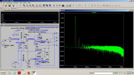
One interesting piece of information I still wanted to share is in the image below.
Already shown in previous images is the fact that the PCM1792 updates the analog output at intervals of 1/(64*192Khz) = 81.38nsec.
In my Bel Canto Dac, all incoming signal is up-sampled to 192Khz.
However when offering the Dac a 44.1/16 multitone test, the first image pair is not found around 192Khz but at 1.536Mhz or 8 times as high.
The second and third image pairs are found at multiples of 1.536Mhz.
I wonder what this means when the PCM1792 is instructed to go in NOS mode.
I suspect that the image pairs are not at multiples of Fs.
If so, can this still be regarded as a NOS Dac in the usual meaning ?
Anyhow, this Dac is a complex machine.
Hans
.
Attachments

See figure 7 and pages 15 and 19 of https://www.ti.com/lit/ds/symlink/pcm1792a.pdf Apparently the PCM1792A has an internal eight times oversampling filter that can be bypassed. The sigma-delta modulators run at a higher clock frequency than the output sample rate of the digital filter, as corresponds with your measurements.
It's never really NOS because the sigma-delta necessarily runs at a much higher frequency than the incoming sample rate, but by bypassing the digital filter, you can get staircase-like waveforms out of it, with lots of ultrasonic quantization noise on top of it because of the sigma-delta modulation.
It's never really NOS because the sigma-delta necessarily runs at a much higher frequency than the incoming sample rate, but by bypassing the digital filter, you can get staircase-like waveforms out of it, with lots of ultrasonic quantization noise on top of it because of the sigma-delta modulation.
Last edited:
I think that it could run in NOS mode but has to be in right justified format only and set apropriate pin to avoid internal oversampling module?
from he datasheet:
The PCM1792A in the external digital filter interface mode supports right-justified audio formats including 16-bit,20-bit, and 24-bit audio data, as shown in Figure 41. The audio format is selected by the FMT[2:0] bits of controlregister 18.
from he datasheet:
The PCM1792A in the external digital filter interface mode supports right-justified audio formats including 16-bit,20-bit, and 24-bit audio data, as shown in Figure 41. The audio format is selected by the FMT[2:0] bits of controlregister 18.
I have a question hoping that someone has a sensible answer.
For the current conveyor I-V, having a constant Zin up to 100Khz is suggested as being a superior quality.
A voltage feedback amp as I-V has a Zin that starts in the mOhm range, climbing with 20dB/oct to somewhere around 1R at 100Khz, this all depending GBW of the used amp.
If a constant Zin over the first 100Khz would be so important, why does nobody advise to insert a 0.5R resistor between Dac output and virt. gnd input of the voltage feedback amp to also get a constant Zin to practically 100Khz ?
Hans
I have a question hoping that someone has a sensible answer.
For the current conveyor I-V, having a constant Zin up to 100Khz is suggested as being a superior quality.
A voltage feedback amp as I-V has a Zin that starts in the mOhm range, climbing with 20dB/oct to somewhere around 1R at 100Khz, this all depending GBW of the used amp.
If a constant Zin over the first 100Khz would be so important, why does nobody advise to insert a 0.5R resistor between Dac output and virt. gnd input of the voltage feedback amp to also get a constant Zin to practically 100Khz ?
Hans
For veryhigh OP Z DACs such as PCM179x super low Z in of I-V is not that critical. There was a thread some time ago where this was all measured.
From memory anything under 30 ohms or so had virtually no effect on distortion.
On the other hand something like an AK4499 is at the opposite end of the spectrum, low IP Z of DAC is important but also *linearity of IP Z.
TCD
I remember @abraxalito recommending for entire multiple order pi filters in front of I/V to cut the grass...wouldn't they raise impedance too?
Transimpedance amps look better for the job although jung's article was aiming in a different direction: https://cfas.waltjung.org/High_Performance_Audio_Stages_Using_TransZ_Amps.pdf
Transimpedance amps look better for the job although jung's article was aiming in a different direction: https://cfas.waltjung.org/High_Performance_Audio_Stages_Using_TransZ_Amps.pdf
Last edited:
If the DAC's output impedance is approaching a true current source (say >100k ohm) then the filter is going to lower that rather than raise it. A lower impedance filter tends to make for a more noisy I/V stage as it increases opamp noise gain.
Ah - so from the point of view of the DAC the impedance looking into the I/V is raised yes, its no longer a virtual ground when a filter is interposed.
Many DACs are designed only to drive into an opamp I/V with virtual GND. AD1862 is one such and I'm fairly sure there are others.
Many DACs are designed only to drive into an opamp I/V with virtual GND. AD1862 is one such and I'm fairly sure there are others.
Last edited:
For veryhigh OP Z DACs such as PCM179x super low Z in of I-V is not that critical. There was a thread some time ago where this was all measured.
From memory anything under 30 ohms or so had virtually no effect on distortion.
That's interesting because Hans recently tried an MFB stage of which the input impedance is low at low and high frequencies and about 22 ohm somewhere in between (it behaves like an LRC parallel network). Contrary to expectations he measured a much degraded distortion. It's still a mystery why.
The op-amp in the circuit sees a load impedance equivalent to a capacitor of a nanofarad or so (I don't remember the exact value) in series with 22 ohm. Maybe that affects the performance of the op-amp in some way or other (even though it didn't in LTSpice). So far we only thought about DAC voltage compliance issues.
Two years ago, although very confused at the time i digged into a converter that i hought would allow me to use two op-amps in parallel with no output offset and lower input noise, never tried to see what would the op-amp input impedance be though: https://www.diyaudio.com/forums/digital-source/336480-stage-town-6.html#post5775288
Attachments
You've two B-E junctions in parallel there, will work a treat in sim as the models will be identical but in practice you'll need some degen Rs (which add noise).
I actually built those circuits, couldn't hear any noise...it worked, maybe not ideally but it worked.I think i'll try sim it again in a few days and use it on pcm1792, but a pcm 1794 would be a bit better for that kind of design.I only tried it with pcm1701 which is a 1ma output dac and you don't get any real advantage unless the current is appreciably higher than that.
The output of PCM1794
Graph 3 is visible best.
Peaks with amplitude 1ma and time 2ns.
And this should be integrated accurately.
This overloads each integral audio operating amplifier.
Sandy,
Could you please tell how exactly and by whom these measerements were made.
The images are quite vaque and not showing the scales in a readable way.
But they show one single peak while my measurements also showed a 1mA 2nsec transient but followed by a few smaller resonance like transients.
These smaller resonances could IMO hardly be caused by the 10mm long and 0.035mm wide PCB trace 0.4mm above a analogue gnd trace terminated with 25R in my case.
Hans
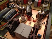
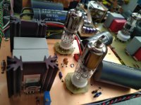
To go a little in the opposite direction, the picture shows my I / V stage and output buffer. 6HM5 is in the grounded grid. The signal ie current from PCM1702 comes to the cathode of the tube.
A long time ago I left discrete and op amp I / V conversion and I replaced it with tubes. I tried everything, even the AD811, but the sound of the tube was much better for me.
However now I am working on a new DAC with TDA1547 where I will have to use discrete or op amp I / V conversion if I intend to use only current outputs, I also have two PCM1794 on hold which in mono mode does not have a suitable tube that could do I / V conversion in a grounded conection.
So I'll go back to discrete or op amp I / V conversion again.
Attachments
To go a little in the opposite direction, the picture shows my I / V stage and output buffer. 6HM5 is in the grounded grid. The signal ie current from PCM1702 comes to the cathode of the tube.
A long time ago I left discrete and op amp I / V conversion and I replaced it with tubes. I tried everything, even the AD811, but the sound of the tube was much better for me.
However now I am working on a new DAC with TDA1547 where I will have to use discrete or op amp I / V conversion if I intend to use only current outputs, I also have two PCM1794 on hold which in mono mode does not have a suitable tube that could do I / V conversion in a grounded conection.
So I'll go back to discrete or op amp I / V conversion again.
When you are fond of tubes, you should build Marcel’s Valve Dac.
Valve DAC from Linear Audio volume 13
Hans
- Home
- Source & Line
- Digital Line Level
- Discrete I-V converter