> My panels are 10mm thick...
Wow, very... solid state 🙂
And last question - how are you going to finish it?
Are there any companies which could make anodizing
of the custom aluminium case/panel?
Wow, very... solid state 🙂
And last question - how are you going to finish it?
Are there any companies which could make anodizing
of the custom aluminium case/panel?
I’m putting together a pga2310 preamp (Russ White’s layout and schematics). I have three questions
1. Will the bypass capacitors value on the datasheet (figure 5) degraded the sound? Russ uses 47uf instead
of 10uf
2. Anyone tried Walter Jung ad815 composite amp as an output buffer?
3. What is the purpose of the -5volt supply?
1. Will the bypass capacitors value on the datasheet (figure 5) degraded the sound? Russ uses 47uf instead
of 10uf
2. Anyone tried Walter Jung ad815 composite amp as an output buffer?
3. What is the purpose of the -5volt supply?
Hey guys,
The 5V rail drops to 4.6 when I run my darwin off of it. Its 5V when the darwin is left unconnected.
Is this normal and OK?
The 5V rail drops to 4.6 when I run my darwin off of it. Its 5V when the darwin is left unconnected.
Is this normal and OK?
maxw said:Hey guys,
The 5V rail drops to 4.6 when I run my darwin off of it. Its 5V when the darwin is left unconnected.
Is this normal and OK?
Bump. Anolog V+ stays at 5V but digital V+ drops to 4.6V when the darwin is connected. The Darwin only draws 38mA so I don't think there is a short or anything. It works fine though. Is this OK?
That actually looks slightly low for the PGA's digital section (recommended 4.75V - 5.5V), but if it's working okay...
maxw said:
Bump. Anolog V+ stays at 5V but digital V+ drops to 4.6V when the darwin is connected. The Darwin only draws 38mA so I don't think there is a short or anything. It works fine though. Is this OK?
Please ignore me if I'm wrong, but r1 (on the schamtic I have) is 10 ohms which 5v goes through to get to pic/pga. 40ma/10ohms/4.6v - that combo seems tailor made for something to do with ohms law (or whatever law is working here). .04x10=(5-4.6). My theory holds up (I think) only if you are getting 5v from the digital side of r1.
Get 5v for darwin from volume pot instead.
jaudio said:I’m putting together a pga2310 preamp (Russ White’s layout and schematics). I have three questions
1. Will the bypass capacitors value on the datasheet (figure 5) degraded the sound? Russ uses 47uf instead
of 10uf
2. Anyone tried Walter Jung ad815 composite amp as an output buffer?
Because of the difference in the pga2310's supply requirements(not to mention the AD815 composite), Im not using Russ White layout.
But can anyone answer the questions I posted earlier?
Thanks
jaudio said:
Because of the difference in the pga2310's supply requirements,Im not using Russ White layout.
But can anyone answer the question I posted earlier?
Thanks
The cap value is not critical
10-100uf is fine.
Any good buffer should work just fine on output. The 815 circuit you mention would probably be just great.
Strange problem when using v1.1 PIC
Hi there,
I recently purchased an assembled Kookaburra from a friend and have been having a lot of fun with it. I received a few extras with it including a PIC labelled v1.1 (the installed PIC was unlabelled).
I decided to connect a 50K log pot in place of the original. I know a logarithmic pot is not ideal, but it's motorized, and I'm too lazy to get up every time I want to change the volume 🙂
So, I turned everything on, sat back on the couch and proceeded slowly turn up the volume. When the pot had travelled only a few degrees there was a sudden burst of full volume sound which triggered the amplifier protection circuit. Oh dear, I thought...
To cut a long story short, after some experimentation I found with the v1.1 PIC, when the 50K log pot is a few degrees from minimum, it causes very short bursts at full volume. These bursts are a fraction of a second, with about 1/2 second gap between them. Once the pot has passed this point, the volume level is low and increases gradually as expected. At least one burst will occur whenever the pot passes this point. With careful adjustment I get the continuous bursts.
This doesn't happen with the original unlabelled PIC, which I guess is v1.0.
If anyone (Russ?) has any ideas about what's causing this I'd be interested.
Best regards,
Andrew.
Motorized pot, right? I would doubt it's the code in the PIC.
Sounds like there is an issue with the POT/WIPER pin where it's somehow losing the ground reference while turning. Is there a away you can check that?
If the PIC were causing that... you'd have to see the POT Hunting wildly while it's being driven.
Sounds like there is an issue with the POT/WIPER pin where it's somehow losing the ground reference while turning. Is there a away you can check that?
If the PIC were causing that... you'd have to see the POT Hunting wildly while it's being driven.
Re: Strange problem when using v1.1 PIC
The "1.1" version was experimental, and should not be used.
It has a mathematical error which kicks in exactly as you say.
The unlabeled PIC most likely has the correct production firmware.
Cheers!
Russ
arjscott said:Hi there,
I recently purchased an assembled Kookaburra from a friend and have been having a lot of fun with it. I received a few extras with it including a PIC labelled v1.1 (the installed PIC was unlabelled).
I decided to connect a 50K log pot in place of the original. I know a logarithmic pot is not ideal, but it's motorized, and I'm too lazy to get up every time I want to change the volume 🙂
So, I turned everything on, sat back on the couch and proceeded slowly turn up the volume. When the pot had travelled only a few degrees there was a sudden burst of full volume sound which triggered the amplifier protection circuit. Oh dear, I thought...
To cut a long story short, after some experimentation I found with the v1.1 PIC, when the 50K log pot is a few degrees from minimum, it causes very short bursts at full volume. These bursts are a fraction of a second, with about 1/2 second gap between them. Once the pot has passed this point, the volume level is low and increases gradually as expected. At least one burst will occur whenever the pot passes this point. With careful adjustment I get the continuous bursts.
This doesn't happen with the original unlabelled PIC, which I guess is v1.0.
If anyone (Russ?) has any ideas about what's causing this I'd be interested.
Best regards,
Andrew.
The "1.1" version was experimental, and should not be used.
It has a mathematical error which kicks in exactly as you say.
The unlabeled PIC most likely has the correct production firmware.
Cheers!
Russ
Re: Re: Strange problem when using v1.1 PIC
Ok, thanks for letting me know. And just want to say thanks for putting the work into this product! I'm thinking of having a go at some of your new kits once they are available.
That's exactly what I first thought. I really thought I'd see the error when measuring the pot. My guess at the v1.1 PIC was just by elimination.
Best regards,
Andrew.
Russ White said:
The "1.1" version was experimental, and should not be used.
It has a mathematical error which kicks in exactly as you say.
The unlabeled PIC most likely has the correct production firmware.
Cheers!
Russ
Ok, thanks for letting me know. And just want to say thanks for putting the work into this product! I'm thinking of having a go at some of your new kits once they are available.
pwillard said:
Sounds like there is an issue with the POT/WIPER pin where it's somehow losing the ground reference while turning. Is there a away you can check that?
That's exactly what I first thought. I really thought I'd see the error when measuring the pot. My guess at the v1.1 PIC was just by elimination.
Best regards,
Andrew.
Kooky
I'm spreading myself thin into lots of projects these days. 😀 Here is what I just soldered together tonight. Took an hour to do it and I must say that the Pear Brothers make a fantastic kit! I still can't get over the attention to detail in the packaging method.
I'm off to see a cabinet maker tomorrow about putting some wood into the metal enclosure I purchased.
I have a funny feeling I'm really going to enjoy this kooky little thing. 😉 I'll be back when it is together with some more comments. I have all the parts to assemble it so I hope it won't be too long.
Thanks a bunch,
Shawn.
Attachments
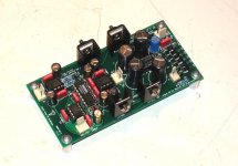
Bright Blue Cap
The 22uF 50V cap got torchured by someone during assembly. So I used one I had in stock as a stand in...more like a stand out! 🙂 Should be fine either way?
Shawn.
The 22uF 50V cap got torchured by someone during assembly.
So I used one I had in stock as a stand in...more like a stand out! 🙂 Should be fine either way?Shawn.
Re: Bright Blue Cap
Brian does all the hard work, and yes he rocks. 😀
As for that cap, it will be just fine. That particular cap acts as a reservoir for the relay. Just about anything would work.
I hope you really enjoy it!
Cheers!
Russ
TomWaits said:The 22uF 50V cap got torchured by someone during assembly.
Shawn.
Brian does all the hard work, and yes he rocks. 😀
As for that cap, it will be just fine. That particular cap acts as a reservoir for the relay. Just about anything would work.
I hope you really enjoy it!
Cheers!
Russ
Hi guys, i built my Kook today, switched on and the LM7812 gets real hot (smells and you can't touch it) I have not tried to measure anything yet other than 2.2volts across the LED socket, Any pointers as to testing process going forward much appreciated....
Cheers mark
Cheers mark
Make sure that you haven't mixed up the lm812 and the lm912. One is +12v and the other is -12v. It matters which side you install them.
(K)
(K)
Thanks Bikedude,
Just checked again just to be sure, no mix up both are where they should be.
Mark
Just checked again just to be sure, no mix up both are where they should be.
Mark
- Status
- Not open for further replies.
- Home
- Amplifiers
- Headphone Systems
- Digitally controlled preamp/headphone amp