LCD 16X01
Hi,
Sorry to make this question. I promise I have tried but to not avail...
I have an LCD with 16 colums and only one row. As long as the important info is in the second row of the display in the original sketch, how is modified this just for only use one row?
I have tried modifiying the sketch with lcd.begin (16,1) and replacing argument 1 by 0 in the several displaying functions i.e. :
lcd.begin(16,1);
lcd.createChar(0,DISC);
lcd.home();
lcd.clear();
lcd.setCursor(0,0);
lcd.print("Arduino Uno Tach");
lcd.setCursor(0,0);
lcd.print("RPM: --.---");
lcd.setBacklight(255);
But I obtain only black blocks with RPM: --: missing the decimals....
My programming skills are very limited so I am hitting a wall.
Thanks in advance and Merry Christmas.....
Not sure I understand.
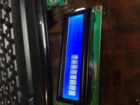
Is the display 16 black blocks (or 8), or black blocks with "RPM---".
Perhaps you could post a picture?
If it is all black blocks (or 8 blocks), the LCD is not getting initialized correctly. Are you using I2C interface or serial? A picture of the Arduino board with wiring may be helpful.
Is the display 16 black blocks (or 8), or black blocks with "RPM---".
Perhaps you could post a picture?
If it is all black blocks (or 8 blocks), the LCD is not getting initialized correctly. Are you using I2C interface or serial? A picture of the Arduino board with wiring may be helpful.
Not sure I understand.
Is the display 16 black blocks (or 8), or black blocks with "RPM---".
Perhaps you could post a picture?
If it is all black blocks (or 8 blocks), the LCD is not getting initialized correctly. Are you using I2C interface or serial? A picture of the Arduino board with wiring may be helpful.
Hi Bill, Thanks....I appreciate...
The display shows 8 blocks with printed in the background RPM: --.
If I change the line lcd.beging from (0,1) to (0,2) there are no blcak dots, only RPM: --.
I am using I2C and the connections at the arduino are the recommended one, SDA, SCL, VCC and GND.
Thanks
Attachments

Last edited:
Do you have a data sheet for the LCD display?
Most 16 x1 displays have character display addresses from 00-0fh, but some have addresses 00-07h for the first 8 characters and 40-47h for the last 8. On 16x2 displays, the 2nd line of 16 character addresses are 40-4fh.
Try adding these lines:
lcd.SetCursor(0,1)
lcd.print("12345678")
Change the first line to:
lcd.begin(16,2)
If you see "12345678" on the second half of the display, then your addresses are 00-07 and 40-4fh and you will have to deal with it accordingly (or get a different display).
Also, check the contrast pot on the I2C PCB is adjusted properly. Before sending data from the Aurduino, adjust the pot so there are black blocks displayed on the LCD (you can disconnect SDA and SCL to prevent the Arduino from sending any data).
Do you have a data sheet for the LCD display?
Most 16 x1 displays have character display addresses from 00-0fh, but some have addresses 00-07h for the first 8 characters and 40-47h for the last 8. On 16x2 displays, the 2nd line of 16 character addresses are 40-4fh.
Try adding these lines:
lcd.SetCursor(0,1)
lcd.print("12345678")
Change the first line to:
lcd.begin(16,2)
If you see "12345678" on the second half of the display, then your addresses are 00-07 and 40-4fh and you will have to deal with it accordingly (or get a different display).
Also, check the contrast pot on the I2C PCB is adjusted properly. Before sending data from the Aurduino, adjust the pot so there are black blocks displayed on the LCD (you can disconnect SDA and SCL to prevent the Arduino from sending any data).
Hi Bill,
Total success...!!!
Activity Icon in the first Character, RPM: always printed and data displayed in the secon half of the display.
Thanks, Thanks, Thanks....
Warmest Regards,
Jorge
Attachments

That's a good solution Jorge; not having to break up the numeric display across the boundary---very smart!
I'm now having ideas about building another controller using 4 bit 7 segment LED display instead. Its obvious I've to alter the program code and Arduino wiring to suit and make it work. It will be a straightforward readout and dashes when it stop. I could integrate it into the SG-4 controller.
I will have to start learning and cooking it up later on. I can easily buy the 7 segment module here at my place and start experimentation.
I've thought about it over and over. Existing 16 X 2 LCD with 2 sets of 7 segment display from SG-4 on the front panel looks odd.
Arduino to 7 segment display.
Using the Serial 7-Segment Display - learn.sparkfun.com
I appreciate anyone to join in to teach me a thing or two.
Lee
I've thought about it over and over. Existing 16 X 2 LCD with 2 sets of 7 segment display from SG-4 on the front panel looks odd.
Arduino to 7 segment display.
Using the Serial 7-Segment Display - learn.sparkfun.com
I appreciate anyone to join in to teach me a thing or two.
Lee
I appreciate anyone to join in to teach me a thing or two.
Lee
Can you let us know which 7-segment display (or type) you plan to acquire?
What you linked earlier refers to a 7-segment display "shield" which allows for the display to connect to the Arduino via I2C (and with very few wires).
Should you want to interface the display directly (with no backpack/shield) you will end up using a lot more pins:
7 Segment Display on Arduino
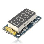
Do you have a photo from the top? I cannot discern what are the connections on the side apart from what I assume is ground.
Do you have a photo from the top? I cannot discern what are the connections on the side apart from what I assume is ground.
Thank you for your help. I'll defer this for a while to study what types of 4 digit displays I can find and put to practice. I was thinking of a suitable display module already configured for 4 pin I2C connected to the Arduino in the same way as the I2C LCD, then alter the code for it to work.
Thank you for your help. I'll defer this for a while to study what types of 4 digit displays I can find and put to practice. I was thinking of a suitable display module already configured for 4 pin I2C connected to the Arduino in the same way as the I2C LCD, then alter the code for it to work.
Yep, I2C should work just fine.
I'm now having ideas about building another controller using 4 bit 7 segment LED display instead. Its obvious I've to alter the program code and Arduino wiring to suit and make it work. It will be a straightforward readout and dashes when it stop. I could integrate it into the SG-4 controller.
Your last sentence gave me pause for concern. Are you attempting to do both the tach and PSU using only one display (on the SG4)? Or will you have 2 displays, one for the tach and the other on the SG4 that are of the same type (LED)?
The latter is entirely possible, the former, not so much....
Your last sentence gave me pause for concern. Are you attempting to do both the tach and PSU using only one display (on the SG4)? Or will you have 2 displays, one for the tach and the other on the SG4 that are of the same type (LED)?
The latter is entirely possible, the former, not so much....
Hi Bill,
I'm sorry if it sounded misleading. Its all independent LED display from each other, there's no sharing of display.
I had ideas for 3 different LED display on the front panel. Arduino tach, SG-4, and Output AC Voltage.
I've already finished building the SG-4 module with a 3rd party 0.56" display and working just fine, Output AC Voltmeter also from another 3rd party purchase that's fitted with 0.56" LED, its now the Arduino tach to convert to LED display too. I'm awaiting delivery of amp module and other stuff which have still not arrived from abroad, possibly due to this festive period.
Last edited:
I think that will be a very good looking solution.
As no one has done the tach with an LED display, please post your results, if you would?
As no one has done the tach with an LED display, please post your results, if you would?
Hi Bill and all here. Its the start of the New Year 2018 this very minute for me here at Malaysia. Happy New Year to all!
I intend to work on the LED display tach soon and will keep you posted on the progress.
Thanks Bill, for the encouragement!
Lee
I intend to work on the LED display tach soon and will keep you posted on the progress.
Thanks Bill, for the encouragement!
Lee
Sketch for LCD16X01 requested by PM
Hi,
Alex requested the modified sketch by PM and as the PM is limited in characters and somebody could consider it useful, here it is. All credits are for Bill (Pyramid) I only did some minor changes to adapt it. Thanks Bill.
Alex:
You have to download the LiquidCrystal_PCF8574.h library and install it in the Arduino Enviroment. Also you have to check if you already have library Wire.h (normally it is in the enviroment). Also you have to select the correct arduino board, in this case it is the Arduino Genuino Uno and the correct programmer AVRISP mkII.
Best Regards
Jorge
Attachments
Hi Jorge,
Thank you a lot.
I already downloaded sketch (arduino_tach_tweaked) and modded it for my LCD. LCD lib (Newliquidcrystal_1.3.5.zip) was downloaded from Adruino site and Wire.h is a part of IDE. So, it seems that all works just fine: YouTube
I observed strange issue during testing for my reflective strips with 1.5mm and 6mm width. RPM readings were defer with different strips.My sensor does have a gain trimmer, but signal was strong even with that tiny strip made of sticky aluminum foil.on black platter. My local surplus store sale these sensors for $1.5. Any advice for strip with in mm?
I would be very interested to bud CG4 and to integrate it with that tachometer for Close Loop Control. However, It seems that generator PCB is available, but MK154 amp is not anymore. Any advice for its substitute?
Than you very much.
Alex
Attachments
Hello Alexkosha.
I used the IR sensor module with TCRT5000 IR LED sensors type. This worked pretty well during my early experimentation. Its got twin LED at the front. Next is if you can find 3M Reflective tape to use.
I used the IR sensor module with TCRT5000 IR LED sensors type. This worked pretty well during my early experimentation. Its got twin LED at the front. Next is if you can find 3M Reflective tape to use.
- Home
- Source & Line
- Analogue Source
- Digital Tachometer for record player (LCD display)