Hi coolmasetr I have ordered "Midas MC21605G12W", did you use hall effect sensor or IR sensor, could you share code you using Midas display.Thanks
Hi,
My code is for the Midas with a I2C serial PCF 8574 based module. There's 2 types, and each with a slightly different hex address. If you solder direct to it, the Midas display will not work and will need a some surgery to make it adapt to it. If its piggy back on direct without any modification, it may burn something on the LCD module. I purposely used the I2C module for less wires and connection hassle. This Midas display is very nice and nearly fried it as I was my 1st time tackling this LCD display for anything. I had to read the Midas datasheet, compare the circuitry to other common LCD and found the difference, solved it by rerouting the I2C module to adapt correctly.
Let me know what you have on hand. I'll try to help.
It will accept either IR or hall effect sensor without any change as long as the trigger is to pin 3.
Hi Thanks for respond, I have ordered in eBay "Midas Displays MC21605G12W-VNMLG 16x2 VATN LCD Display Negative Mode Green" and I have TCRT5000 Obstacle Avoidance IR also I have "Hall sensor module using M44 switch" I have "Arduino Genuino UNO Rev 3 Atmega328. I would like to build same your turntable tachometer. Please guide me how to build this tachometer. what surgery need to be do on LCD. Your code you have posted on "Diyaudio"? Thanks Rajkumar
Hi tauro0221,
I need your help, I have "LCD Display Module Blue Backlight for Arduino LCD1602 IIC I2C TWI 1602 Serial TO" I have also Arduino UNO, and TCRT5000-IR-Infrared-Line-Track-Follower-Sensor-Obstacle-Avoidance-Module
I have connected wire to Display SDA & SCL to Main board pin 17 & 18 SDA and SCL. TCRT500 signal wire to main board pin 3, I have load your code file" turntable_rpm_display_intrp_01_08_2017_2.ino" display not showing any charters!? Please help he where I am wrong. Rajkumar
Hi,
Sorry, but the program will not run with the LCD1602 IIC I2C TWI 1602. If you read the heading it is said that it is for the NEWHAVEN display NHD-0216K3Z-NSW-BBW. The display it is a TTL serial communication. You can use it but you may need to change the all display output call format. Attached it is one that it is for the I2C. You need to connect the SDA to A4 and the CLK to A5. These two address are hard core in the library. The sensor goes to pin 3. It is so long that I do not do anything with the program. See if it works OKAY for you.
Sorry, but the program will not run with the LCD1602 IIC I2C TWI 1602. If you read the heading it is said that it is for the NEWHAVEN display NHD-0216K3Z-NSW-BBW. The display it is a TTL serial communication. You can use it but you may need to change the all display output call format. Attached it is one that it is for the I2C. You need to connect the SDA to A4 and the CLK to A5. These two address are hard core in the library. The sensor goes to pin 3. It is so long that I do not do anything with the program. See if it works OKAY for you.
Attachments
I've to try recall what I've done. My LCD is Midas MC21605G12W-VNMLR (red on black) whereas yours is green version. The circuitry is the same for both. The difference lie (compared to lcd 1602) is to reroute the I2C VR potentiometer ground terminal to Vee (pin 15) at the Midas display. This involve a bit of careful surgery to the I2C adapter. Do this surgery BEFORE soldering piggyback to the LCD. It'll be a pain to separate it in case of any mistake. Perhaps hook all up to a breadboard before making anything permanent. The I2C VR have to be entirely desoldered removed from the adapter pcb, isolate the ground terminal by cutting round that VR pin point, then connect by wire to pin 15 at LCD. I don't know if you can do this successfully but hope you can if you insist on using the Midas display.
About the commonly found I2C 1602 adapter. You may be supplied with 2 types of chips. PCF8574T or PCF 8574AT. Both are the same chip but different address 0x3f or 0x27
Use Arduino I2C scanner to find out the address and use that.
Code for Midas LCD
--------------------------------
#include <Wire.h>
#include <LiquidCrystal_I2C.h>
LiquidCrystal_I2C lcd(0x27, 2, 1, 0, 4, 5, 6, 7, 3, POSITIVE); //* Midas LCD I2C enabled
---------------------------------
I too is new to all these in the beginning and had to figure it out from whatever knowledge I could find to use to make it all work. Its been quite flawless ever since. I didn't even know that a lot of various LCD could be different. I thought they were universal, even the I2C module, how wrong I was but learned quite a bit after completion.
I've gone one step further, I2C OLED display instead of LCD. Cute little thing, had to rewrite the whole code to adapt to the OLED display.
Last edited:
Hi Thanks, I try my best with my limited knowledge. If you have drawing 12C 1602 will helpful. I have found some detail following link I2C connection to LCD screen (PIC18F4553 / PCF8574) | Microchip . Thanks
Hi Thanks, I try my best with my limited knowledge. If you have drawing 12C 1602 will helpful. I have found some detail following link I2C connection to LCD screen (PIC18F4553 / PCF8574) | Microchip . Thanks
Again, remove the i2c VR pot, isolate the ground terminal, link that isolated terminal with wire to Pin 15 after soldering the VR pot back to the module.
Try it out with a breadboard to see if it works.
I had some difficulty getting the correct address for my LCD controller as it did not match the documentation that came with it. If the controller uses a PCF8574, the address can be 0x20-0x27, depending upon the jumpers on the controller PCB. If the controller is PCF8574, the range of addresses are 0x38-0x3F. The line:
LiquidCrystal_I2C lcd(0x27, 2, 1, 0, 4, 5, 6, 7, 3, POSITIVE); //* Midas LCD I2C enabled
has to have the correct address of the I2C controller to work correctly (in this example, the first parameter in the parenthesis: 0x27). There is a sketch called 'scanner' that will test all 127 possible addresses and report the address of any devices that respond, in hex format (0x00 through 0x7F). This can be useful for verifying connection and address of an LCD controller connected to the I2C bus. The Scanner code is available here:
https://playground.arduino.cc/Main/I2cScanner?action=sourceblock&num=1
Also, as coolmaster has posted, the contrast control has to be working properly and be adjusted properly or you will not see a display. You should be able to adjust the contrast control without any data being sent to the LCD, the display will show one line of solid "block" characters and one line that is blank (no characters). When you see this on the display, the contrast is set correctly. At this point, try sending a text message to the display using the address reported by the Scanner sketch.
Pyramid is spot on! Thanks for further elaboration on the subject.
We may be buying the I2C piggyback module from anywhere or any vendor, its not always the case yours maybe the same as what I received. Yes, the scanner sketch is very useful here.
We may be buying the I2C piggyback module from anywhere or any vendor, its not always the case yours maybe the same as what I received. Yes, the scanner sketch is very useful here.
Hi,
Also do not solder the piggyback I2C to the LCD. Use the same socket they use in the Arduino pins connections. You can remove it easy if you have some problems with the display. If you a LCD make sure the piggyback it is not solder to the display. Normally I buy the ones with the connector looses.
Also do not solder the piggyback I2C to the LCD. Use the same socket they use in the Arduino pins connections. You can remove it easy if you have some problems with the display. If you a LCD make sure the piggyback it is not solder to the display. Normally I buy the ones with the connector looses.
I was itching to try replacing my existing UNO with the less frills Arduino Nano. Any opinions?
Last edited:
Hi I am new to this program loading file, I have doubt how to loading file to Aruino IDE, copy "turntable rpm.txt" complete file to Arduino IDE software page or change file format from .txt to .ino than open through Arduino IDE? I have to copy all charter in txt to IDE or only 'void setup' and "void loop" sorry for the question. Thanks once again
Rajkumar-
The code tauro0221 provided was an early version. This is a later version with some improvements and it will work with I2C interface to a PCF8574A controller. You may still have to tweak that part of the code to work with your particular display, but the rest of the code will work with an Arduino Uno R3.
To load the file, you should copy it to your computer and change the file name to Tach.ino (we cannot post a file with .ino extension on DIYAudio so it had to be changed to .txt).
Attachments
Last edited:
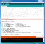
I have try to loading file you given "Tach" also try another old file there was error message on screen Arduino IDE, I have used Arduino Uno Chinese board and check loading example file board working good, used LCD "1602 16x2 LCD Character Display + IIC/I2C/TWI/SPI Serial interface Board Module" module chip PCF8574AT. I have attached board and screenshot error. please help me.


Attachments
Last edited:
You probably need to add the full path to the header file (*.h) or add you project directory to the path where the compiler looks for header files.
Tom
Tom
Ensure that you have the PCF8574 library installed in the Arduino IDE. If not, you will need to download and install it. See this link for help:
Arduino - Libraries
Arduino - Libraries
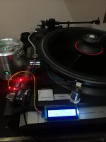
Dear Pyramid, As per your instruction I have installed libraries for PCF8574 than file can verify loading successfully, but still not seen any character, then address try change as per txt file than when enter 0x3f load again start working I can seen RPM display  I am very happy you people doing grate support. Please find picture my turntable "Kenwood L-07D' this is legendary from Kenwood, this table direct drive, I have modified "Direct & Belt Drive. Thank you all who help. Rajkumar
I am very happy you people doing grate support. Please find picture my turntable "Kenwood L-07D' this is legendary from Kenwood, this table direct drive, I have modified "Direct & Belt Drive. Thank you all who help. RajkumarAttachments
Hi Coolmaster, I have received Midas Display since yesterday now I'm waiting for another 12C adapter, you're 100% correct existing 12C adapter not able to remove from 1602 2X16 LCD. Once received 12C adapter, I will try to modify 12C adapter VR ground isolate from PCB board solder wire reroute to Midas display pin 15 Vee - negative output. I will update when complete conversion Midas & 12C adapter. Thanks
- Home
- Source & Line
- Analogue Source
- Digital Tachometer for record player (LCD display)