The calibration pot can be 500R (the lowest-resistance available in the 10-turn version). That would make the source impedance change between 100R - 500R during calibration. I have 5k now.
The measured opamp load resistor can also be e.g. 100R (e.g. 2Vmax/100R = 20mA). I have 1k now.
The LPF for WB noise could be about 500R impedance on both sides approx.
All this will increase the chain attenuation (no major problem with 24bit ADC), as well as skew the frequency response (also no problem when measuring THD).
The problem with DUT load resistor of 100R is the opamp THDs are usually stated for 1k load. 100R will definitely produce much higher distortion. That is why I chose 1k in the current version.
You do not need to load the opamp under test with 100 ohms, if soundcard input impedance is 1M. Soundcard just has to be driven from low impedance, i.e. low resistance in series with the opamp under test, 100 ohm - 1k should be OK.
To keep the calibration and measurement paths similar, I can keep the 1k opamp load resistor and use 1k calib multiturn pot instead of the existing 5k. Plus a permament wideband noise LPF (Zin about 1k) right at the soundcard input jack.
But will the measured opamp THD change significantly if driving the 1k load resistor and the 1k Zin LPF in parallel? I am afraid it will.
But will the measured opamp THD change significantly if driving the 1k load resistor and the 1k Zin LPF in parallel? I am afraid it will.
Depends, maybe. The LPF begins with pure resistance of 390 ohm, so it should not be that bad. And 4,7nF impedance at 10kHz is 3,3kohm.
Right, I have simulated the filter with 10nF caps, to go lower with the cutoff freq.
I will order the 1k multiturns and try the new setup, thanks a lot.
I will order the 1k multiturns and try the new setup, thanks a lot.
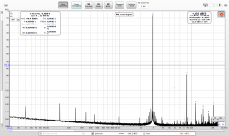
Replacing the E-MU 0404 headphone output 2114 with OPA1622 (and dropping the output serial resistors from 220R to 30R) raised a direct loopback distortion from 0.0018% to 0.0082%. Perhaps the artificial ground in the OPA->DIP8 adapter?
The third harmonic (limitation) shot up over -90dB
An externally hosted image should be here but it was not working when we last tested it.
The third harmonic (limitation) shot up over -90dB
Attachments
Last edited:
Hm, the other channel (direct, no VD) is OK, slightly better than 2114 values. Perhaps I slightly damaged the RC filter of one channel during soldering, no idea..
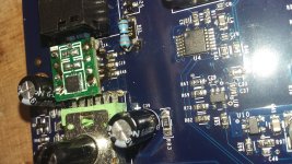
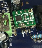
Replacing the opamp did take magnification glasses 🙂
Replacing the opamp did take magnification glasses 🙂
Attachments
Perhaps the artificial ground in the OPA->DIP8 adapter?
The ground pin is where the internal compensation cap returns. IIRC, datasheet says it should be connected to ground or performance will suffer.
Thanks, I will try to ground it.
Changing the output series R from 220 to 30 may cause some instability due to cap loading. If it was the artificial ground, why would it work earlier with that? Or did I misunderstand?
Jan
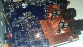
Original - SO8 2114, new - 10pin OPA1622 with compensation cap ground pin. The DIP8 adapter carrying OPA1622 contains a voltage divider for artificial ground - that one will be properly grounded instead, once I get back from family vacations.
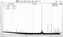
I cut the trace from opamp GND pin to the artificial ground divider and connected it to ground around. Loopback THD dropped from 0.082% to 0.0016% for the left channel and from 0.0018% to 0.0015% for the right channel. The original loopback THD for 2114 was 0.0018% in both channels. OPA1622 brings a small but measurable improvement in THD, but my main reason is (hopefully) the increased output current capability.
Without the GND pin grounded compensation was unstable, 2nd harmonic kept varying. Now the compensated profile is stable.
Thanks for the hint!
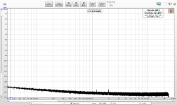
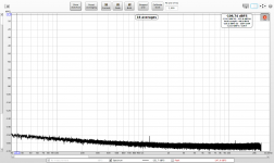
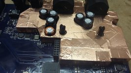
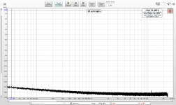
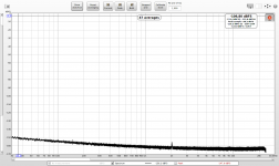
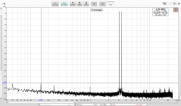
When the soundcard was disassembled I 3D printed a shield for the input stage. It has a very slight improvement compared to measurements in https://www.diyaudio.com/forums/equ...nsation-measurement-setup-23.html#post5828984 (those were for 256kHz FFT, the new ones are 1M FFT). In both cases measured with no input, with output 1211Hz@-1dBFS.
Without the GND pin grounded compensation was unstable, 2nd harmonic kept varying. Now the compensated profile is stable.
Thanks for the hint!
When the soundcard was disassembled I 3D printed a shield for the input stage. It has a very slight improvement compared to measurements in https://www.diyaudio.com/forums/equ...nsation-measurement-setup-23.html#post5828984 (those were for 256kHz FFT, the new ones are 1M FFT). In both cases measured with no input, with output 1211Hz@-1dBFS.
Attachments
Loopback THD dropped from 0.082% to 0.0016%
Of course should be from 0.0082% 🙂
Implemented new method for finding zero time for multitone (time it took from all fundamentals at zero phase to reach current phase combination). The method works with any number of tones at arbitrary frequency combination, but the rest of the tool currently supports only 2 tones.
Screenshots
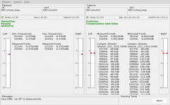
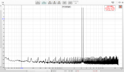
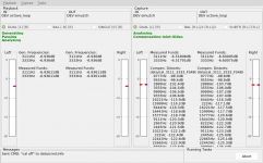
1) 3,111Hz + 3,333Hz at -6.3dB each - a hard signal for the E-MU soundcard
2) Joint-sides compensating 97 IMD distortions takes about 70% of an older Xeon core.
Screenshots
1) 3,111Hz + 3,333Hz at -6.3dB each - a hard signal for the E-MU soundcard
2) Joint-sides compensating 97 IMD distortions takes about 70% of an older Xeon core.
Attachments
Last edited:
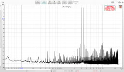
Actually the list of compensated distortions on the tool (and REW too) revealed the left channel was clipping hard (all IMDs worse than -90 dB)
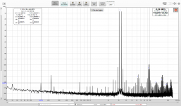
Slightly lowered generated signal results in a very different picture.
Slightly lowered generated signal results in a very different picture.
Attachments
Last edited:
Can you compensate a sawtooth wave and then show the extracted residual? Then you could plot it with output voltage (or current) vs error voltage and you would have an interesting error sweep chart showing discontinuities at crossover and saturation near the rails.
I cut the trace from opamp GND pin to the artificial ground divider and connected it to ground around. Loopback THD dropped from 0.082% to 0.0016% for the left channel....
...Without the GND pin grounded compensation was unstable, 2nd harmonic kept varying. Now the compensated profile is stable.
The developer of the OPA1622 mentioned in another thread - AFAIR - that you could connect that pin to - (VEE) instead,. That is the solution used on adapters available from Japan. As you seem to have the perfect setup to check if that equals GND in performance - maybe you could spare a minute to try?
Can you compensate a sawtooth wave and then show the extracted residual? Then you could plot it with output voltage (or current) vs error voltage and you would have an interesting error sweep chart showing discontinuities at crossover and saturation near the rails.
I am afraid I do not understand 🙂
maybe you could spare a minute to try?
The adapter is buried deep in the soundcard, kind of delicate soldering, I do not want to fuss with it anymore 🙂
But I have another OPA1622 I want to measure with my setup once I make a new calibration adapter with lower impedances. I will have to handle the GND pin, I can try both variants.
- Home
- Design & Build
- Equipment & Tools
- Digital Distortion Compensation for Measurement Setup